PROGRAMMING SCHOOL
RoboPRO programs for TXT - TX interface
1. COMBI SENSOR - SIMPLE COMPASS15. PHOTO SENSOR - ANALOGUE (1)
2. ENCODER MOTOR - INPULSE COUNTING16. IR SENZSOR FISCHERTECHNIK - LINE (3) - MOTOR CONTROL
3. I2C Module - Digital Sensor Control - ONLY TX Interface17. IR SENSOR FISCHERTECHNIK - LINE(2)
4. Action Control (Wheel) INPUT Gear (FT037157) (3)18. IR SENSOR FISCHERTECHNIK - LINE (1)
5. Wheel Turn Control INPULS Gear (FT037157) (2)19. PHOTO SENSOR (TRANSISTOR) (2)
6. Wheel Turn Control INPLS Gear (FT037157) (1)20. PHOTO SENSOR (TRANSISTOR) (1)
7. LOGIC WITH VARIABLE - FOLLOW THE LINE - a simple example21. LIGHT CONTROL WITH MINI-SWITCH
8. LOGIC WITH VARIABLE - FOLLOW THE LINE - a simple example22. LIGHT CONTROL - MINI-SWITCH
9. COLOR SENSOR (2)23. DC MOTOR CONTROL
10. COLOR SENSOR (1)24. THREE LIGHT CONTROL - TRAFFIC LIGHTS
11. ULTRASOUND SENSOR25. TWO LIGHT CONTROL
12. PHOTO SENSOR - ANALGUE (4)26. TWO LIGHTS CONTROL
13. PHOTO SENSOR - ANALOGUE (3)27. LIGHT CONTROL
14. PHOTO SENSOR - ALALOGUE (2)

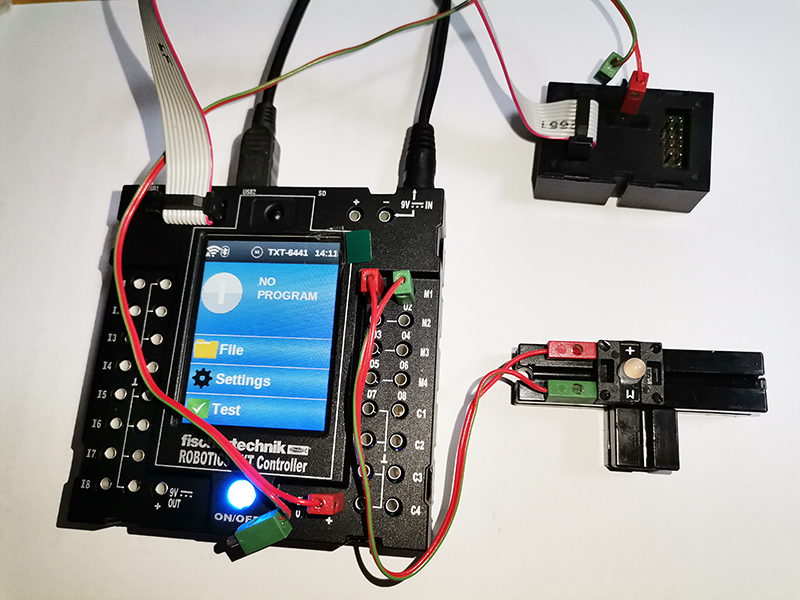
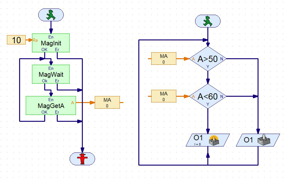
COMBI SENSOR - SIMPLE COMPASS
spajanje027_rpt.jpgRoboPro027T.jpg
WIRING:
Turning the sensor horizontally, changes the value of the direction read. When the sensor is turned in the reading direction between 50 and 60, the LED lights up.
PROGRAM TASK:

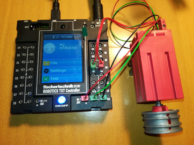
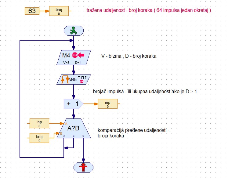
ENCODER MOTOR - INPULSE COUNTING
spajanje026_rpt.jpg 	RoboPro026T.jpg
WIRING:
Connect the ENCODER motor to the M4 output. Connect the wires to the counter at C4 and 9V. Like on the picture. IMPORTANT: MOTOR NUMBER (M4) AND COUNTER (C4) MUST BE THE SAME.
PROGRAM TASK:
By mcounting the pulse (step) the motor should make one turn. Approximately 64 steps for one turn. Try different speeds and step numbers.

I2C Module - Digital Sensor Control - ONLY TX Interface
spajanje025_rpt.jpgRoboPro025T.jpg
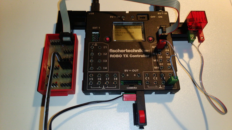
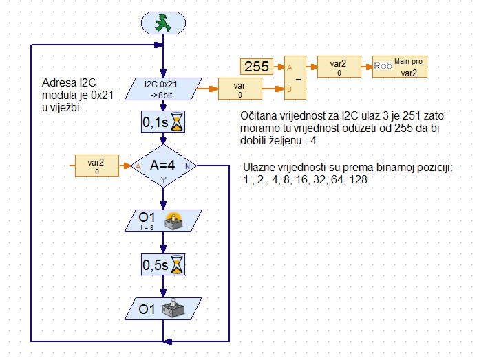
WIRING:
Connect the I2C module via a 6 pin cable to the EXT2 TX interface connector. Connect the LAMP to OUTPUT O1. Connect the button to the 3 I2C connector. Use the ADDRESS of your I2C module in the program. KEEP ATTENTION OF THE RIGHT-CONNECTED CONNECTOR CONNECTED TO THE I2C MODULE, IF DO NOT DO A SHORT CIRCUIT CONNECTION!
PROGRAM TASK:
Pressing the button should turn on the flashlight half a second

Action Control (Wheel) INPUT Gear (FT037157) (3)
spajanje024_rpt.jpgRoboPro024T.jpg
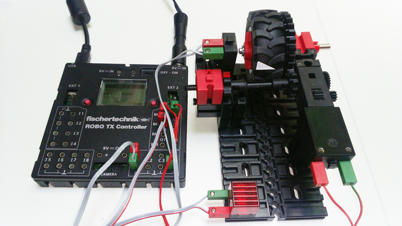
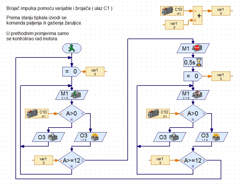
WIRING:
Connect the MOTOR to OUTLET M1, MINI-SWITCH to INPUT C1, and LAMP to OUTPUT O3.MINI-SWITCH is mounted next to the INPULS Gear.
PROGRAM TASK:
With the help of INPULS GEAR and the MINI-SWITCH, the wheel should be rotated to one side for a certain number of pulses, then the other side for a certain number of inpulse. When turning the wheel, the LIGHT should be illuminated each time the button is pressed (has an inpulse) and is switched off each time the button is not pressed. Instead of turning on or off the light bulb, you can perform some other action.

Wheel Turn Control INPULS Gear (FT037157) (2)
spajanje023_rpt.jpgRoboPro023T.jpg
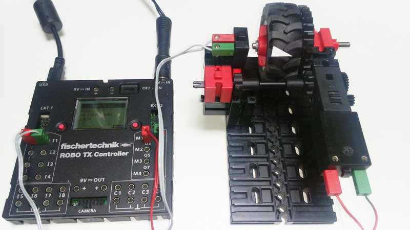
WIRING:
Connect the MOTOR to OUT M1 and MINI-SWITCH to INPUT C1.MINI-SWITCH is mounted next to INPULS Gear.
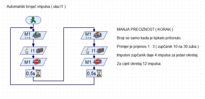
PROGRAM TASK:
With the INPULS GEAR and MINI-SWITCH, the wheel should be turned full circle into one, then to the other side.

Wheel Turn Control INPLS Gear (FT037157) (1)
spajanje022_rpt.jpgRoboPro022T.jpg
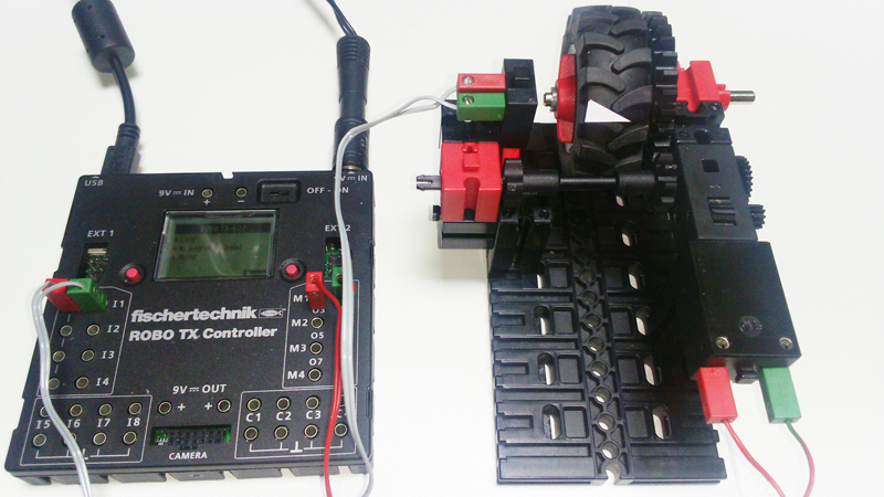
WIRING:
Connect the MOTOR to OUT M1 and MINI-SWITCH to INPUT C1.Type is mounted next to INPULS Gear.
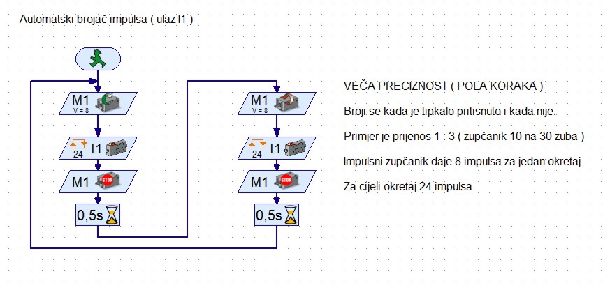
PROGRAM TASK:
With the INPULS GEAR and MINI-SWITCH, the wheel should be turned full circle into one, then to the other side.

LOGIC WITH VARIABLE - FOLLOW THE LINE - a simple example
spajanje021_rpt.jpgRoboPro021T.jpg
WIRING:
Connect the LEFT motor to OUT M1 (O1-green, O2-red). Connect the RIGHT motor to OUT M2 (O3-green, O4-red). The plugs on the motors from left to right: (green, red), (red, green). Connect the RIGHT IR sensor to INPUT I1 (blue / yellow) and I2 (blue), and LEFT IR sensor on INPUT I3 (blue) and I4 (blue / yellow).
PROGRAM TASK:
The vehicle is follow the line with the sensor status control via sumar variable.

LOGIC WITH VARIABLE - FOLLOW THE LINE - a simple example
spajanje020_rpt.jpgRoboPro020T.jpg
WIRING:
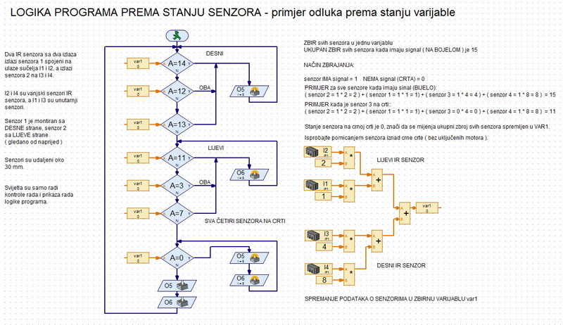
Connect the RED light (left) to OUTPUT O6, and YELLOW (right) to OUTPUT O5. Connect the RIGHT IR sensor to INPUT I1 (blue / yellow) and I2 (blue), and LEFT IR sensor on INPUT I3 (blue) and I4 (blue / yellow).
PROGRAM TASK:
This is an example for testing the main logic with information from sensors. The program logic is branched to the aggregate state of the IR sensor and can be combined in a variety of ways. The same reading system can be used for other sensors.

COLOR SENSOR (2)
spajanje019_rpt.jpgRoboPro019T.jpg
WIRING:
Connect the RED light to OUT 1 (O1) and GREEN to OUT 2 (O2). Connect the COLOR sensor to the power supply and INPUT 1 (I1).
PROGRAM TASK:
When the sensor above the RED surface should turn on the RED light, and when GREEN GREEN lights up. When the sensor above the WHITE surface, both lights need to be turned OFF.

COLOR SENSOR (1)
spajanje018_rpt.jpgRoboPro018T.jpg
WIRING:
Connect the RED light to OUT 1 (O1) and GREEN to OUT 2 (O2). Connect the COLOR sensor to the power supply and INPUT 1 (I1).
PROGRAM TASK:
When the sensor above the RED surface should turn on the RED light, and when GREEN GREEN lights up. When the sensor above the WHITE surface, both lights need to be turned OFF.

ULTRASOUND SENSOR
spajanje017_rpt.jpgRoboPro017T.jpg
WIRING:
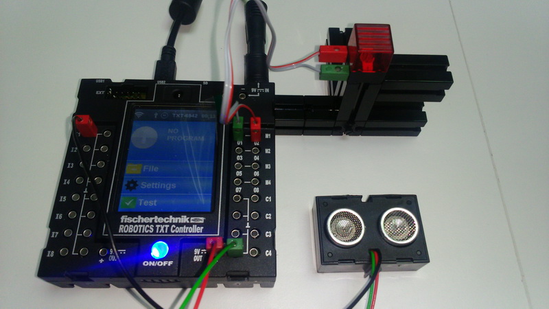
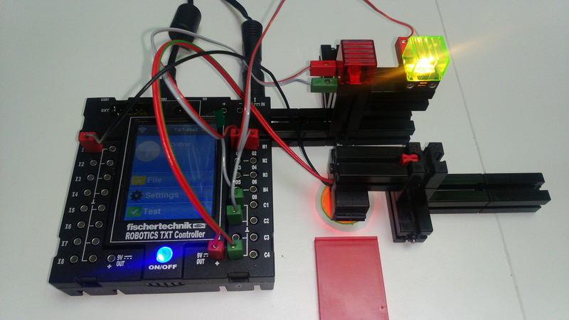
Connect LIGHT to Output 1 (M1 or O1). Connect the ULTRASONIC to Power Supply and sensor to INPUT 1 (I1).
PROGRAM TASK:
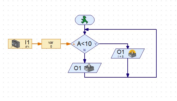
When the sensor approaches a subject at a smaller distance of 10 cm, the LIGHT is to be switched on. Use the VARIABLE to controll the sensor value. Try with other distances.

PHOTO SENSOR - ANALGUE (4)
spajanje016_rpt.jpgRoboPro016T.jpg
WIRING:
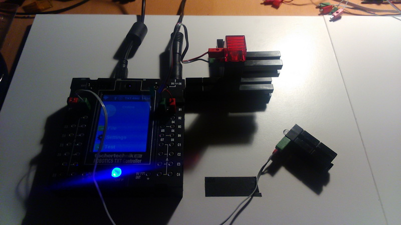
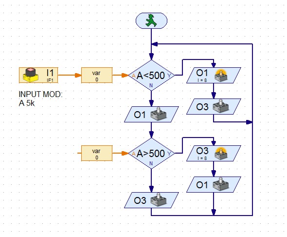
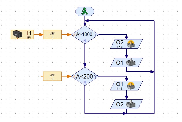
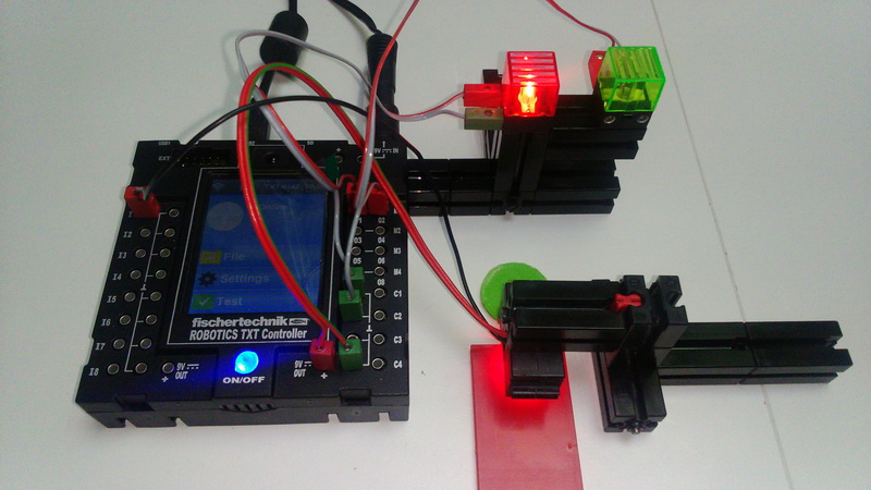
Connect RED light to output 1 (M1 or O1), and GREEN light to output 3 (M2 or O3). Connect the PHOTO Sensor (PHOTO LED or PHOTO RESISTOR (NOT the LED transistor) to input 1 (I1). Adjust the values for comparison (<500 and> 500) to your sensor.
PROGRAM TASK:
When the PHOTO sensor is brightened, the RED light should turn on, and when dimly lit GREEN light should on.

PHOTO SENSOR - ANALOGUE (3)
spajanje015_rpt.jpgRoboPro015T.jpg
WIRING:
Connect the LAMP to the output 1 (M1 or O1). Connect the PHOTO Sensor (PHOTO LED or PHOTO RESISTO , NOT the LED transistor) to input 1 (I1).
PROGRAM TASK:
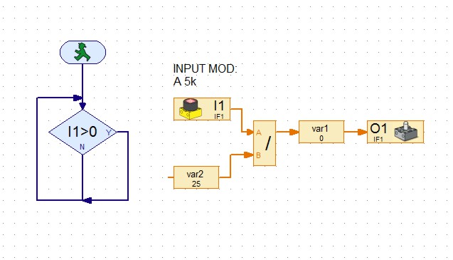
The light intensity of the lamp should indicate the brightness of the sensor's brightness. If the sensor is heavily illuminated, the light bulb should light up and vice versa.

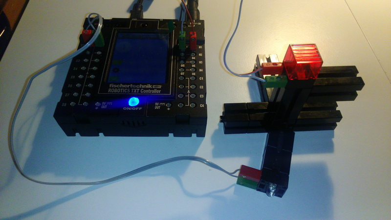
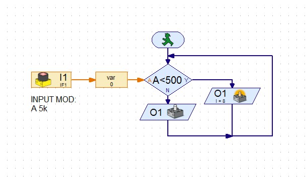
PHOTO SENSOR - ALALOGUE (2)
spajanje014_rpt.jpgRoboPro014T.jpg
WIRING:
Connect the BULB to the output 1 (M1 or O1). Connect the PHOTO Sensor (PHOTO LED or PHOTO RESISTANT, NOT the LED transistor) to input 1 (I1). Adjust the value (<500) to your sensor.
PROGRAM TASK:
By turning the sensor in the direction of light (daylight or lighting) the LIGHT must be switched on. When turned from the light, it should be turned OFF. The program should use the VARIABLE to display the output value of the sensor.

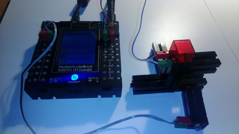
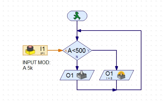
PHOTO SENSOR - ANALOGUE (1)
spajanje013_rpt.jpgRoboPro013T.jpg
WIRING:
Connect the BULB to the output 1 (M1 or O1). Connect the PHOTO Sensor (PHOTO LED or PHOTO RESISTANT, NOT the LED transistor) to input 1 (I1). Adjust the value (<500) to your sensor.
PROGRAM TASK:
By turning the sensor in the direction of light (daylight or lighting) the LIGHT must be switched ON. When turned from the light, it should beswitched OFF.

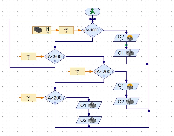
IR SENZSOR FISCHERTECHNIK - LINE (3) - MOTOR CONTROL
spajanje012_rpt.jpgRoboPro012T.jpg
WIRING:
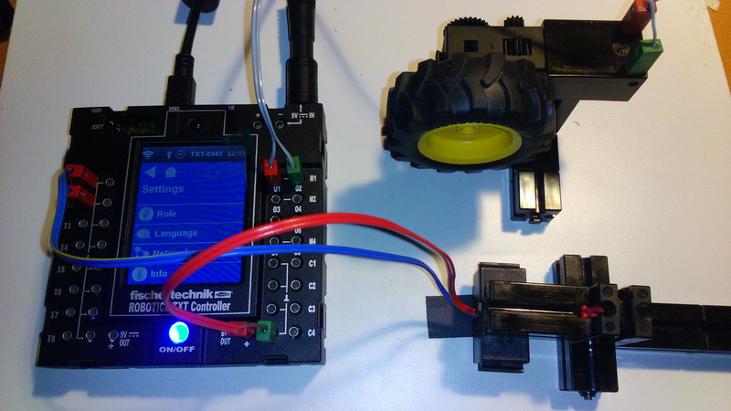
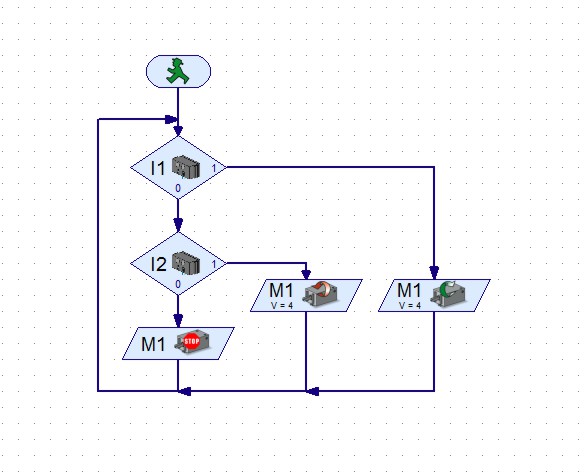
Connect the motor to OUT M1 (O1 + O2). Connect the IR sensor to the INPUT 1 and 2 input (I1 + I2).
PROGRAM TASK:
When the left sensor finds the line, the WHEEL (motor) must start to rotate to one side, and when the right sensor finds the line, the WHEEL (motor) must start to rotate to the other side. When both sensors have found a line, the WHEEL (motor) needs to be stopped.

IR SENSOR FISCHERTECHNIK - LINE(2)
spajanje011_rpt.jpgRoboPro011T.jpg
WIRING:
Connect the RED light to OUT 1 (O1) and GREEN to OUT 2 (O2). Connect the IR sensor to the INPUT 1 and 2 input (I1 + I2).
PROGRAM TASK:
When the left sensor detects the line, the RED light lights up, and when the right sensor finds the line GREEN light. When both sensors are on line, the light bulbs turn ON and OFF alternately.

IR SENSOR FISCHERTECHNIK - LINE (1)
spajanje010_rpt.jpgRoboPro010T.jpg
WIRING:
Connect the RED light to OUT 1 (O1) and GREEN to OUT 2 (O2). Connect the IR sensor to the INPUT 1 and 2 input (I1 + I2).
PROGRAM TASK:
When the left sensor detects the line, the RED lights up, and when the right sensor finds the line GREEN light. When both sensors are in the line, the RED lights up.

PHOTO SENSOR (TRANSISTOR) (2)
spajanje009_rpt.jpgRoboPro009T.jpg
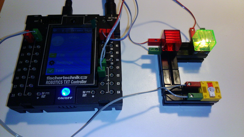
WIRING:
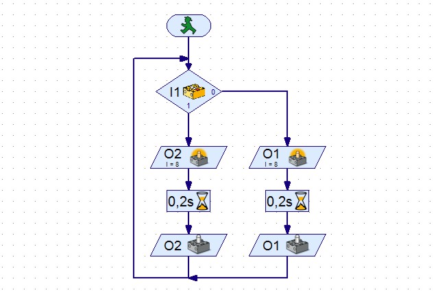
Connect the RED light to OUT 1 (O1) and GREEN to OUT 2 (O2). Connect the PHOTOSENSOR to INPUT 1 (I1) and the light that illuminates the photo sensor to output 3 (O3).
PROGRAM TASK:
Turn on the light that illuminates the sensor. When the photo sensor has a signal, the RED light should light for 0.2 seconds. If the photo sensor does not have a signal, the GREEN lamp should be turned on for 0.2 seconds.

PHOTO SENSOR (TRANSISTOR) (1)
spajanje008_rpt.jpgRoboPro008T.jpg
WIRING:
Connect the RED light to OUT 1 (O1) and GREEN to OUT 2 (O2). Connect the PHOTO SENSOR to INPUT 1 (I1).
PROGRAM TASK:
When the photo sensor has a signal, the RED indicator light should start for 0.2 seconds. If the photo sensor does not have a signal, the GREEN lamp should be turned on for 0.2 seconds.

LIGHT CONTROL WITH MINI-SWITCH
spajanje007_rpt.jpgRoboPro007T.jpg
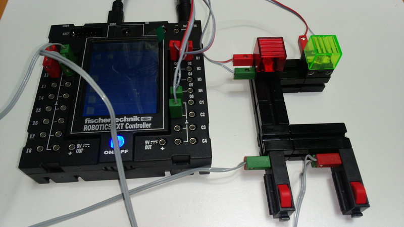
WIRING:
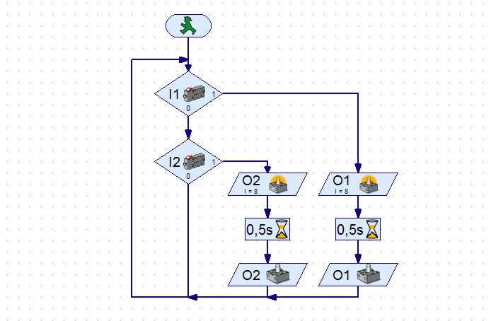
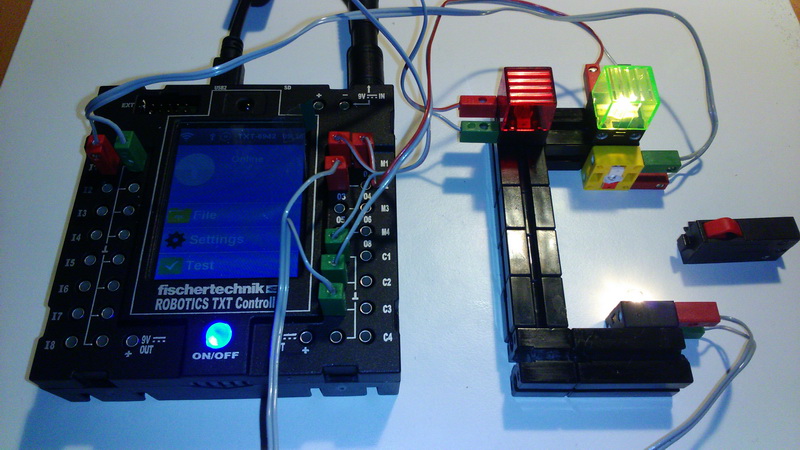
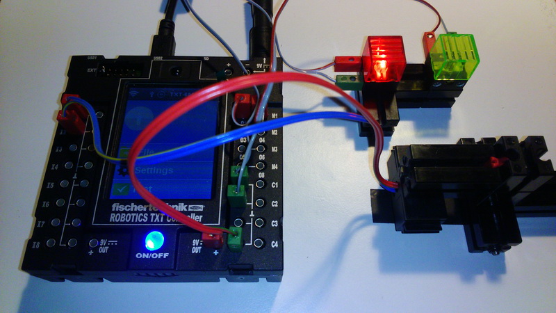
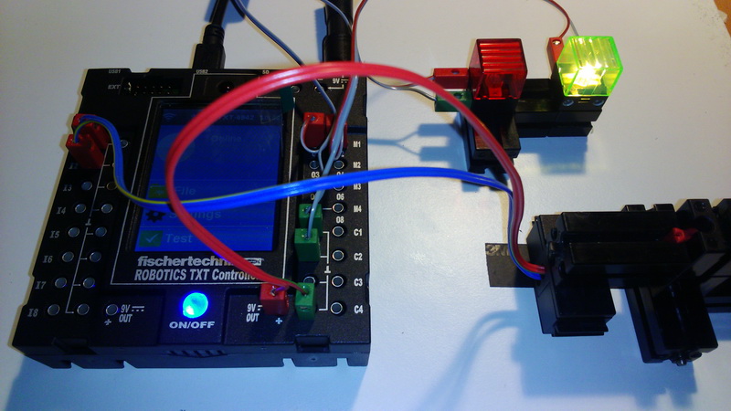
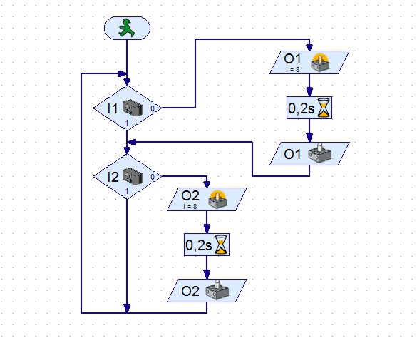
Connect the RED light to OUT 1 (O1), and the GREEN light to OUTPUT 2 (O2). Connect MINI-SWITCH 1 to INPUT 1 (I1) and MINI-SWITCH 2 to INPUT 2 (I2).
PROGRAM TASK:
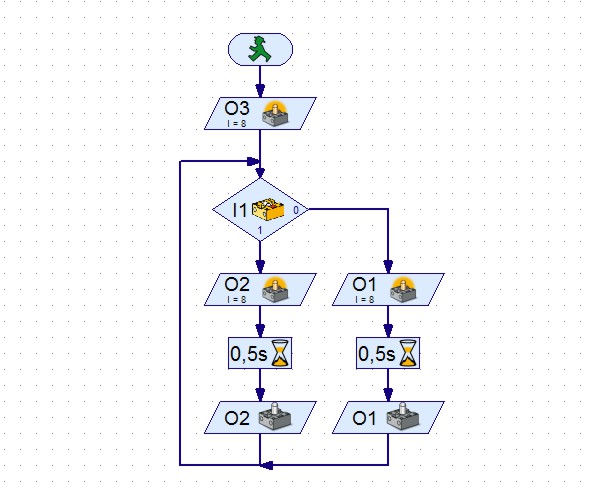
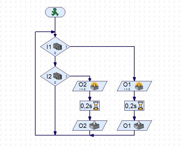
Pressing the MINI-SWITCH 1 button will light up the RED light, and pressing MINI-SWITCH 2 GREEN light will light up. Repeat.

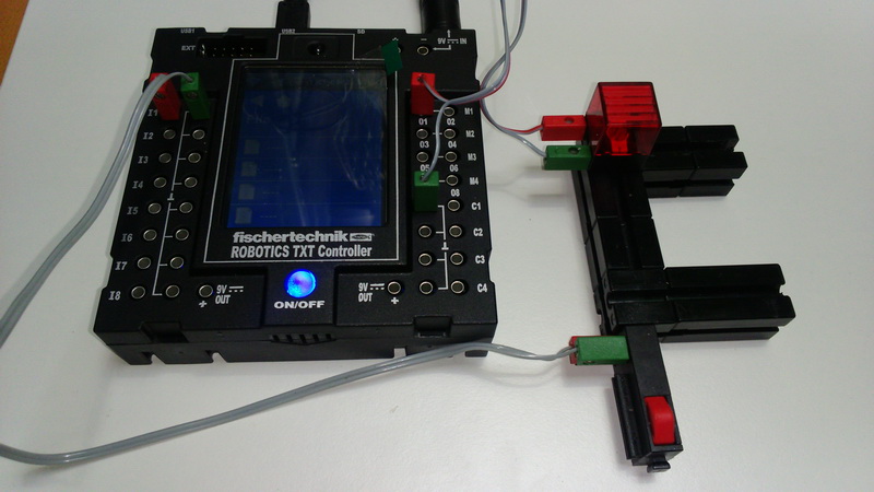
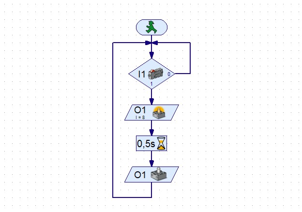
LIGHT CONTROL - MINI-SWITCH
spajanje006_rpt.jpgRoboPro006T.jpg
WIRING:
Connect the light to OUT 1 (O1). Connect MINI-SWITCH to INPUT 1 (I1).
PROGRAM TASK:
After the button on MINI-SWITCH is pressed, the lamp lights up for 1 second. Then turn it off. Repeat.

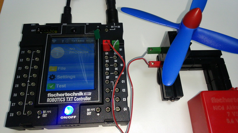
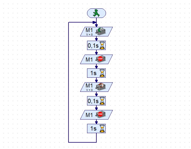
DC MOTOR CONTROL
spajanje005_rpt.jpgRoboPro005T.jpg
WIRING:
Connect motor to OUTPUT 1 (M1 O1+O2).
PROGRAM TASK:
The motor should run on one side 100 milliseconds. Stop the motor for 1 second. Run the motor to the other side for 100 milliseconds. Stop the motor for 1 second. Repeat.

THREE LIGHT CONTROL - TRAFFIC LIGHTS
spajanje004_rpt.jpgRoboPro004T.jpg
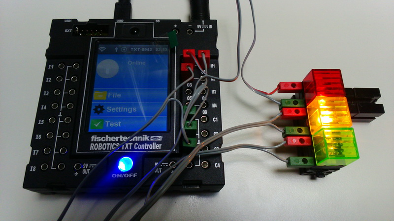
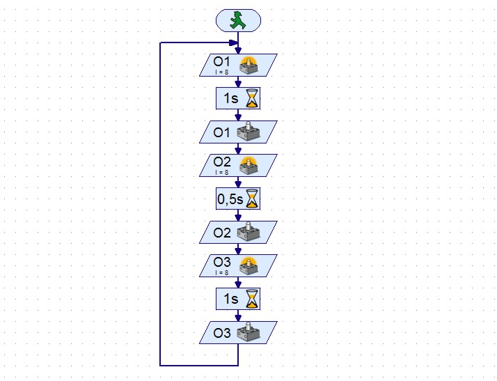
WIRING:
Connect the RED light to OUT 1 (O1), and YELLOW to Output 2 (O2) and GREEN to OUT 3 (O3).
PROGRAM TASK:
Turn on the RED light for 1 second. Turn off the RED and turn on the YELLOW lamp for 0.5 seconds. Shut YELLOW and turn on the GREEN lamp for 1 second. Repeat.

TWO LIGHT CONTROL
spajanje003_rpt.jpgRoboPro003T.jpg
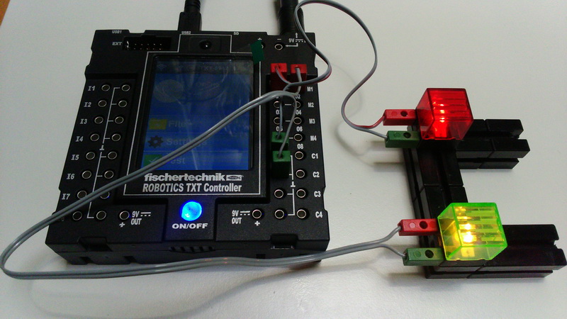
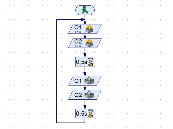
WIRING:
Connect the RED lamp to OUT 1 (O1) and GREEN to output 2 (O2).
PROGRAM TASK:
Turn on the red and green lights for 0.5 seconds. Turn off the red and green light for 0.5 seconds. Repeat.

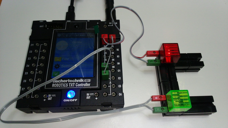
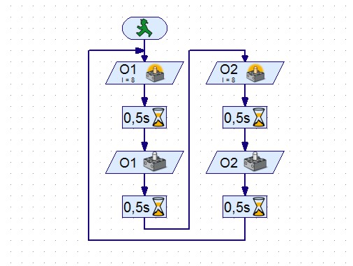
TWO LIGHTS CONTROL
spajanje002_rpt.jpgRoboPro002T.jpg
WIRING:
Connect the RED lamp to OUT 1 (O1) and GREEN to output 2 (O2).
PROGRAM TASK:
Turn on the red light for 0.5 seconds. Turn off the red light for 0.5 seconds. Turn on the green light for 0.5 seconds. Shut down the green light for 0.5 seconds. Repeat.

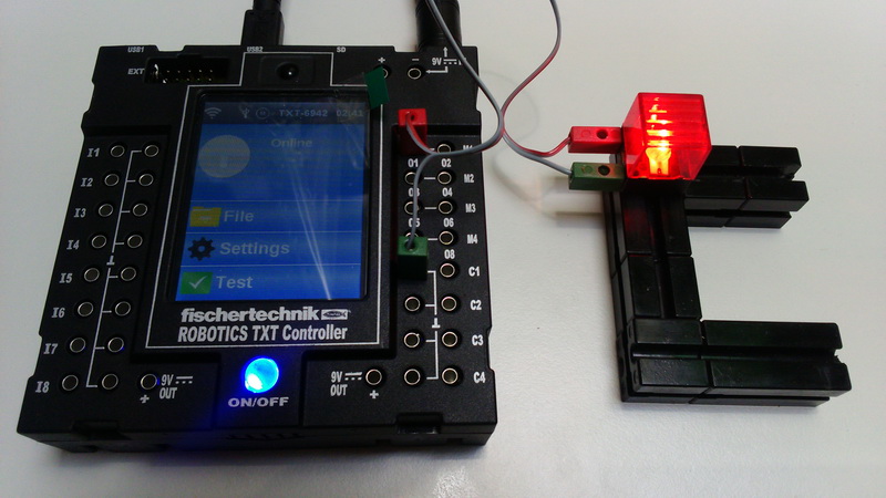
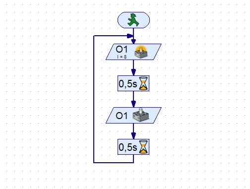
LIGHT CONTROL
spajanje001_rpt.jpgRoboPro001T.jpg
WIRING:
Connect the light to OUT 1 (O1).
PROGRAM TASK:
Turn on the light for 0.5 seconds. Turn off the light for 0.5 seconds. Repeat.