| PROGRAMMING SCHOOL | RoboPRO programs for TXT - TX interface |
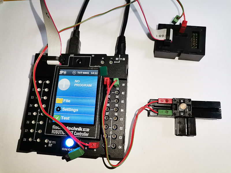
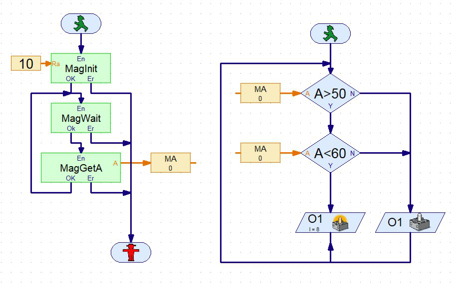
| 1. | COMBI SENSOR - SIMPLE COMPASS | 15. | PHOTO SENSOR - ANALOGUE (1) | ||||||
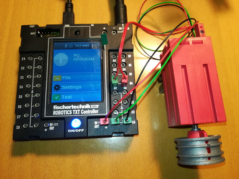
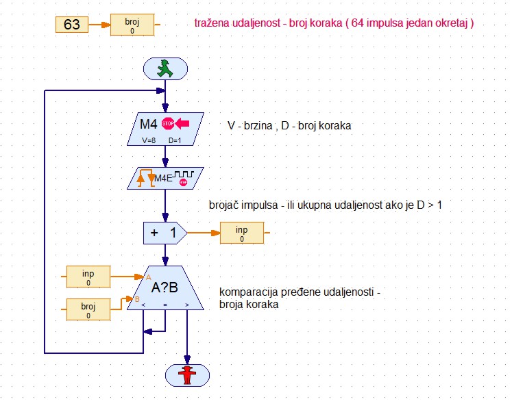
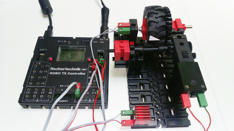
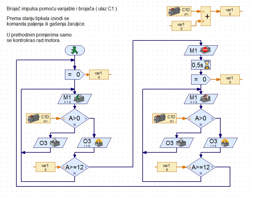
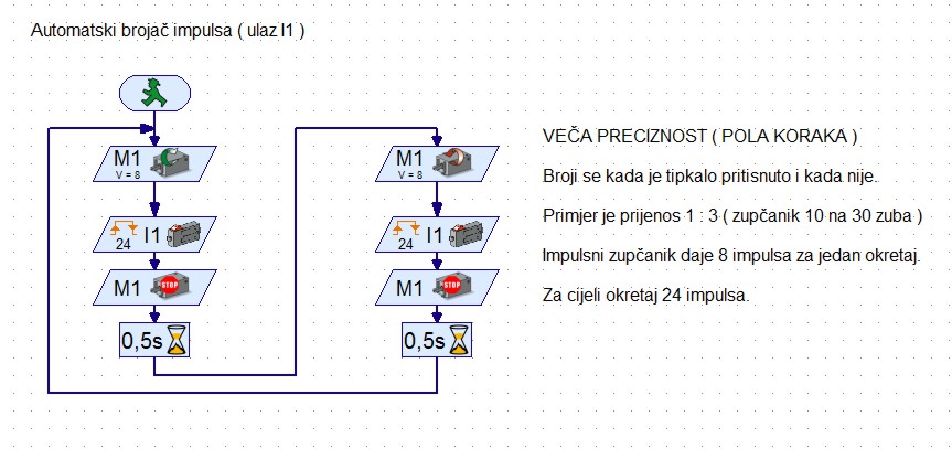
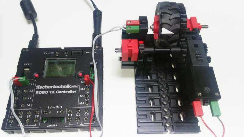
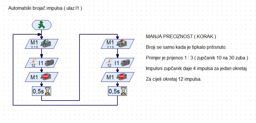
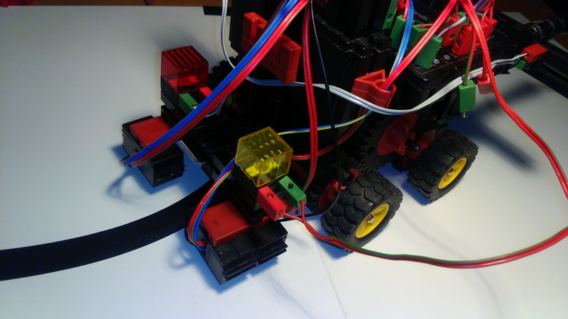
| 2. | ENCODER MOTOR - INPULSE COUNTING | 16. | IR SENZSOR FISCHERTECHNIK - LINE (3) - MOTOR CONTROL | ||||||
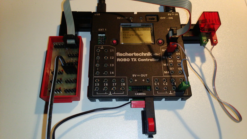
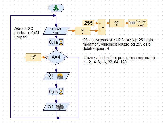
| 3. | I2C Module - Digital Sensor Control - ONLY TX Interface | 17. | IR SENSOR FISCHERTECHNIK - LINE(2) | ||||||
| 4. | Action Control (Wheel) INPUT Gear (FT037157) (3) | 18. | IR SENSOR FISCHERTECHNIK - LINE (1) | ||||||
| 5. | Wheel Turn Control INPULS Gear (FT037157) (2) | 19. | PHOTO SENSOR (TRANSISTOR) (2) | ||||||
| 6. | Wheel Turn Control INPLS Gear (FT037157) (1) | 20. | PHOTO SENSOR (TRANSISTOR) (1) | ||||||
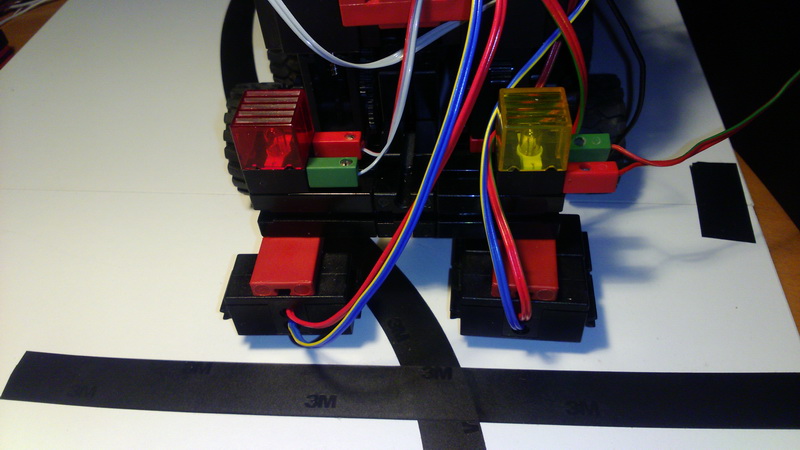
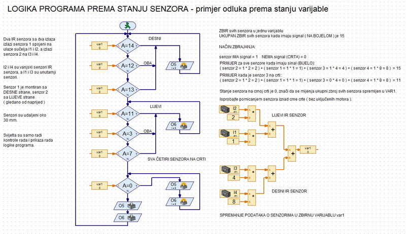
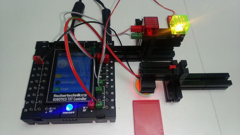
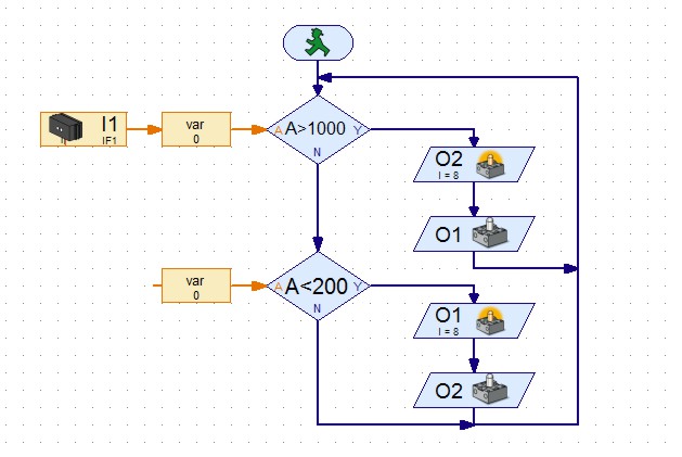
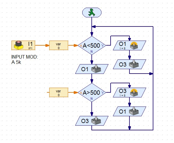
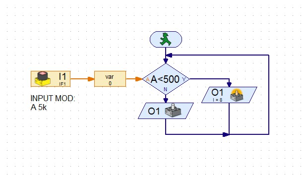
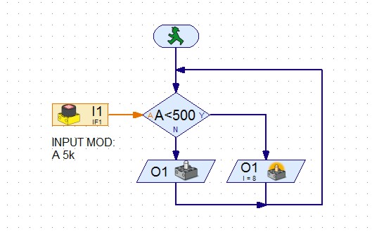
| 7. | LOGIC WITH VARIABLE - FOLLOW THE LINE - a simple example | 21. | LIGHT CONTROL WITH MINI-SWITCH | ||||||
| 8. | LOGIC WITH VARIABLE - FOLLOW THE LINE - a simple example | 22. | LIGHT CONTROL - MINI-SWITCH | ||||||
| 9. | COLOR SENSOR (2) | 23. | DC MOTOR CONTROL | ||||||
| 10. | COLOR SENSOR (1) | 24. | THREE LIGHT CONTROL - TRAFFIC LIGHTS | ||||||
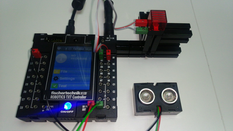
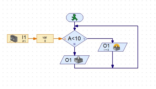
| 11. | ULTRASOUND SENSOR | 25. | TWO LIGHT CONTROL | ||||||
| 12. | PHOTO SENSOR - ANALGUE (4) | 26. | TWO LIGHTS CONTROL | ||||||
| 13. | PHOTO SENSOR - ANALOGUE (3) | 27. | LIGHT CONTROL | ||||||
| 14. | PHOTO SENSOR - ALALOGUE (2) | ||||||||
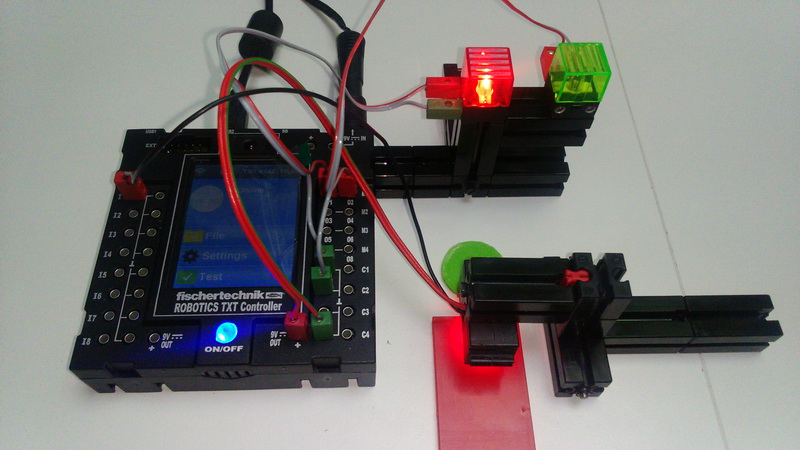
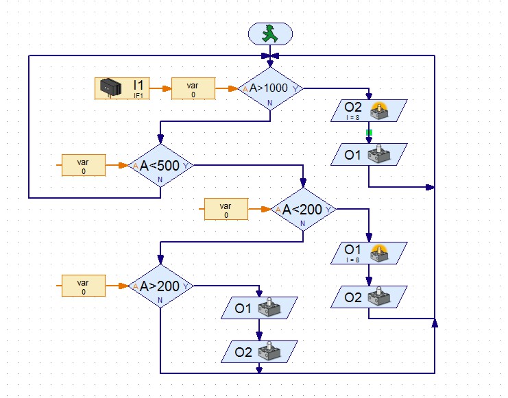
| |||||||||||||||||||||||||||||||||||||||||||||||||||||||||||||||||||||||||||||||||||||||||||||||||||||||||||||||||||||||||||||||||||||||||||||||||||||||||||||||||||||||||||||||||||||||||||||||||||||||||||||||||||||||||||||||||||||||||||||||||||||||||||||||||||||||||||||||||||||||||||||||||||||||||||||||||||||||||||||||||||||||||||||||||||||||||||||||||||||||||||||||||||||||||||||||||||||||||||||||||||||||||||||||||||||||||||||||||||||||||||||||||||||||||||||||||||||||||||||||||||||||||||||||||||||||||||||||||||||||||||||||||||||||||||||||||||||||||||||||||||||||||||||||||||||||||||||||||||||||||||||||||||||||||||||||||||||||||||||||||||||||||||||||||||||||||||||||||||||||||||||||||||||||||||||||||||||||||||||||||||||||||||||||||||||||||||||||||||||||||||||||||||||||||||||||||||||||||||||||||||||||||||||||||||||||||||||||||||||||||||||||||||||||||||||||||||||||||||||||||||||||||||||||||||||||||||||||||||||||||||||||||||||||||||||||||||||||||||||||||||||||||||||||||||||||||||||||||||||||