| PROGRAMMING SCHOOL | Arduino MEGA-F5 / T5 |
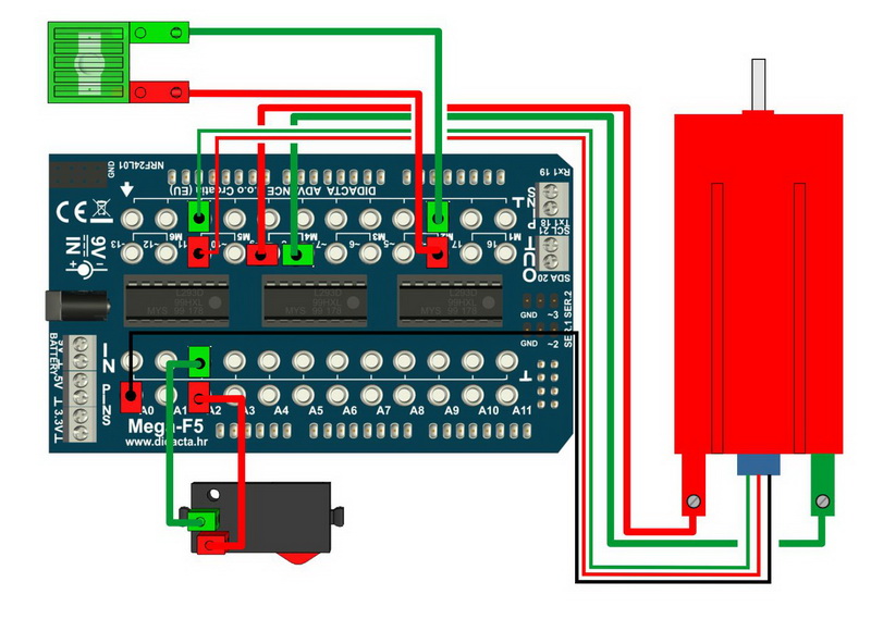
| 1. | STEP MOTOR | 15. | MAGNETIC SENSOR (DIGITAL) | ||||||
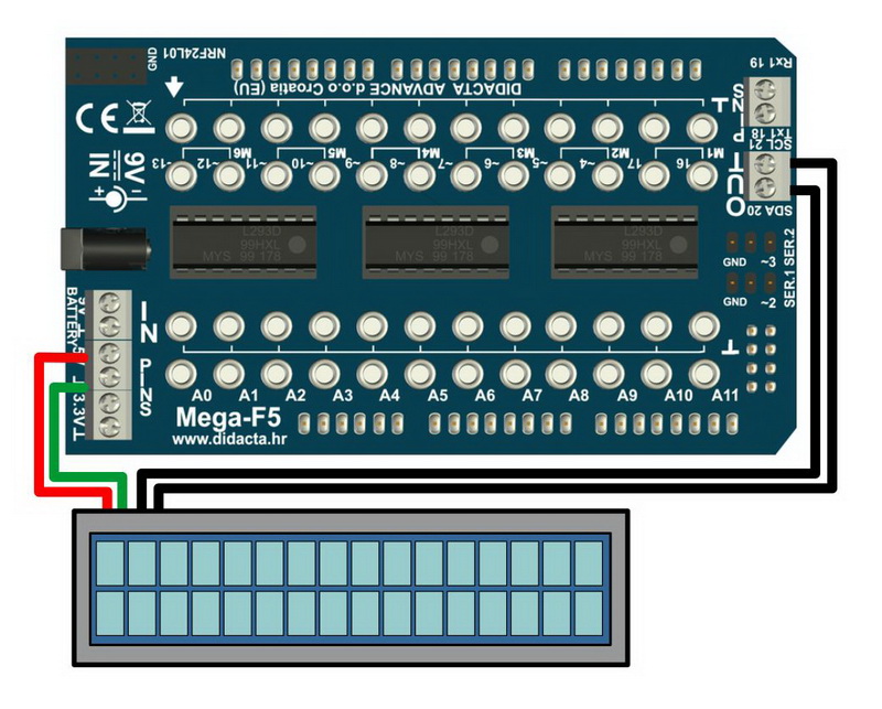
| 2. | I2C - LCD 2 x 16 | 16. | HEAT SENSOR (ANALOGUE) | ||||||
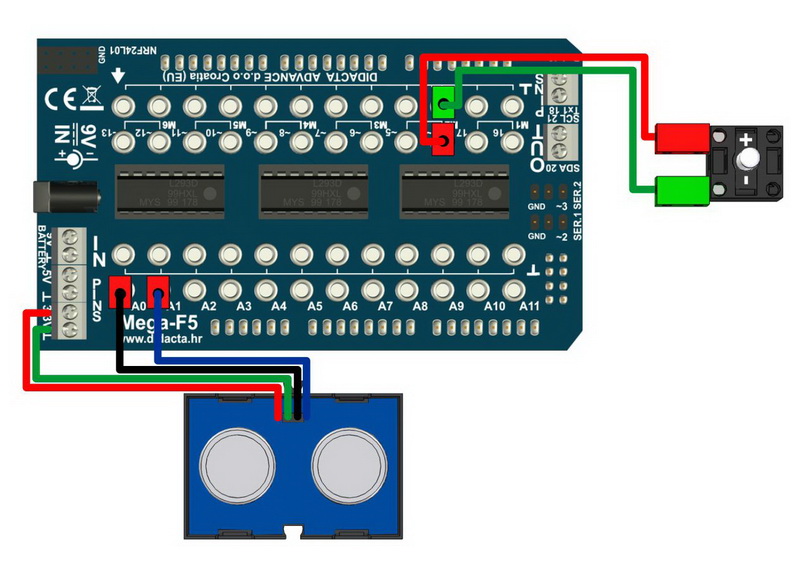
| 3. | CAR + ULTRASONIC SENSOR | 17. | IR SENSOR (ANALOGUE) | ||||||
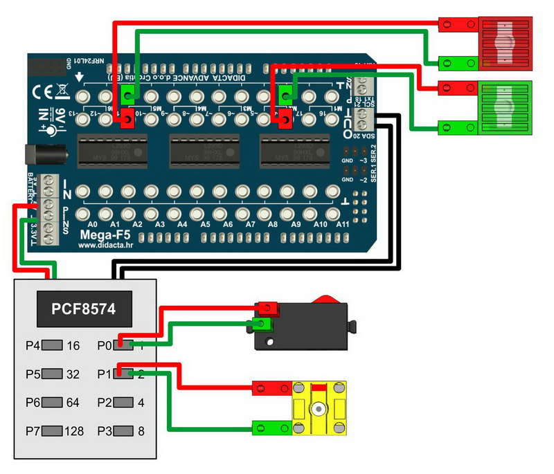
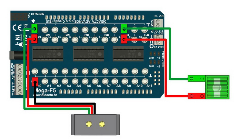
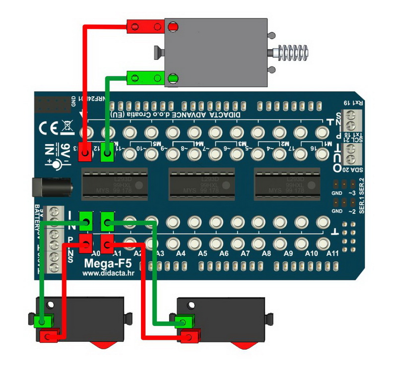
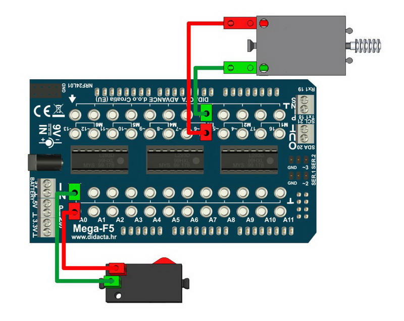
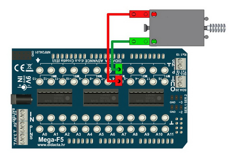
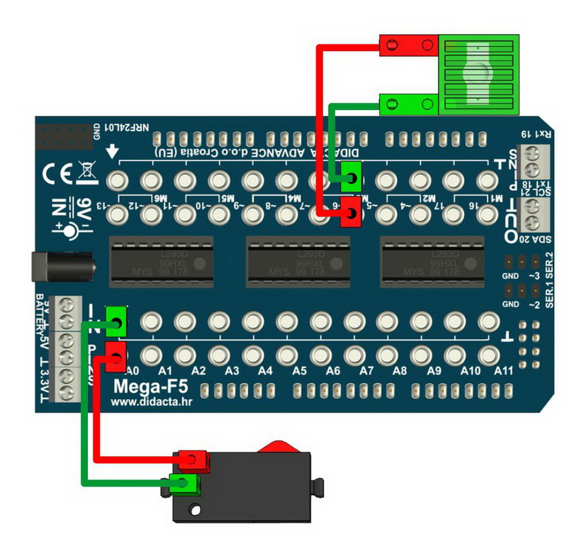
| 4. | BARRIER: Photo sensor + Micro Switch | 18. | IR SENSOR (DIGITAL) | ||||||
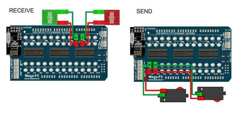
| 5. | COMMUNICATION - NRF24L01 | 19. | DC MOTOR - SPEED CONTROL (ANALOGUE) | ||||||
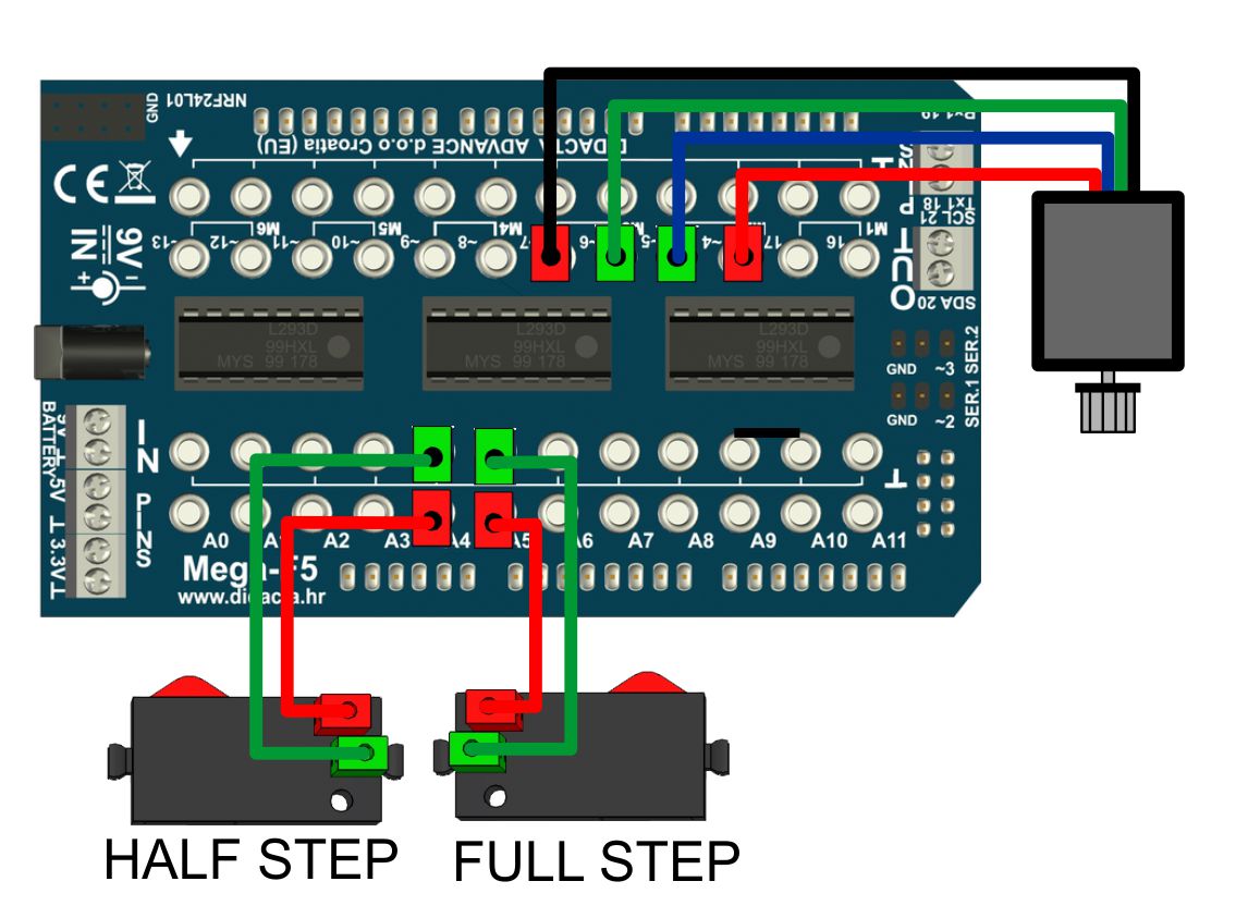
| 6. | ENCODER MOTOR - HALF STEP - BETTER PRECISION | 20. | DC MOTOR - TWO WAYS ROTATION (DIGITAL) | ||||||
| 7. | ENCODER MOTOR - STEP - LESS PRECISE | 21. | DC MOTOR - ONE WAY ROTATION (DIGITAL) | ||||||
| 8. | RX - TX COMMUNICATION | 22. | DC MOTOR (DIGITAL) | ||||||
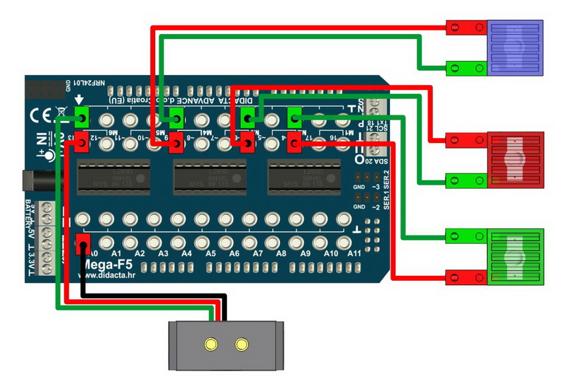
| 9. | I2C COMMUNICATION | 23. | PHOTO SENSOR - LED LIGHT (ANALOGUE) | ||||||
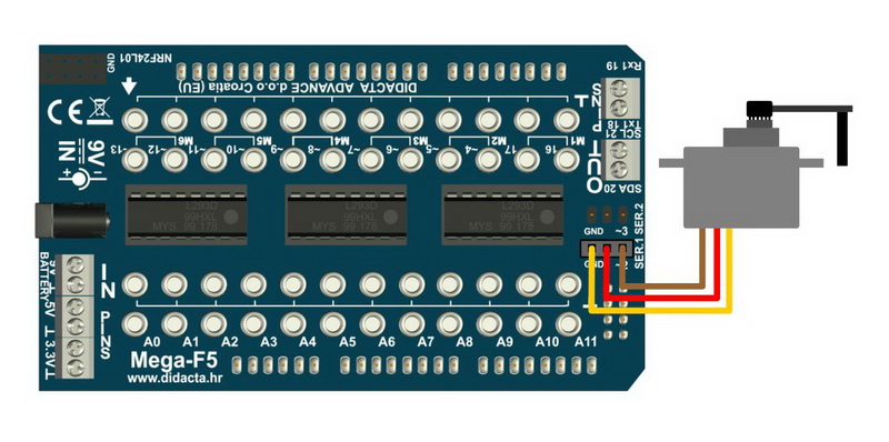
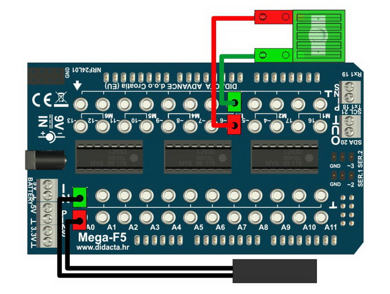
| 10. | SERVO MOTOR | 24. | PHOTO SENSOR - LED LIGHT (DIGITAL) | ||||||
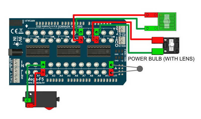
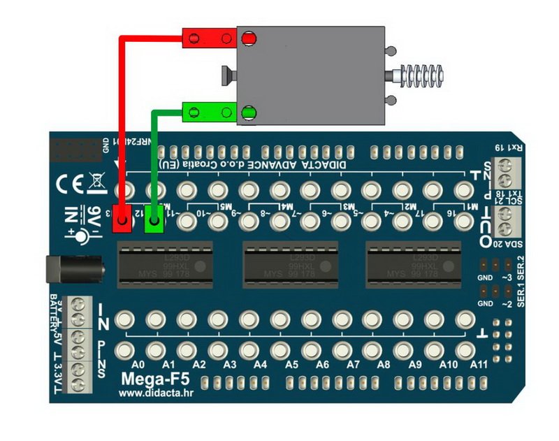
| 11. | ULTRASOUND SENSOR (ANALOGUE) | 25. | LED LIGHT - MICRO SWITHCH (ANALOGUE) | ||||||
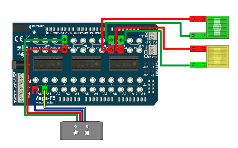
| 12. | ULTRASOUND SENSOR (DIGITAL) | 26. | LED LIGHT (ANALOGUE) | ||||||
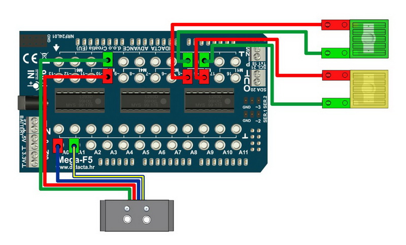
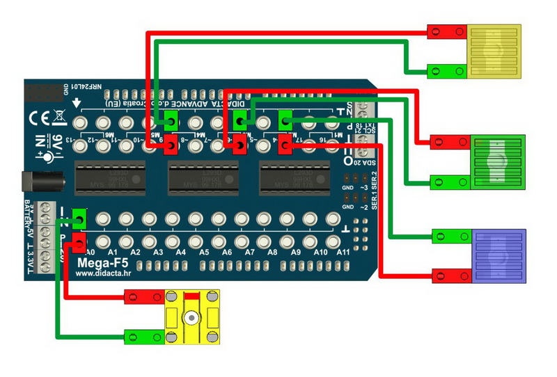
| 13. | COLOR SENSOR - BLACK LINE | 27. | LED LIGHT - MICRO SWITCH (DIGITAL) | ||||||
| 14. | COLOR SENSOR - COLORS | 28. | LED LIGHT (DIGITALY) | ||||||
| |||||||||||||||||||||||||||||||||||||||||||||||||||||||||||||||||||||||||||||||||||||||||||||||||||||||||||||||||||||||||||||||||||||||||||||||||||||||||||||||||||||||||||||||||||||||||||||||||||||||||||||||||||||||||||||||||||||||||||||||||||||||||||||||||||||||||||||||||||||||||||||||||||||||||||||||||||||||||||||||||||||||||||||||||||||||||||||||||||||||||||||||||||||||||||||||||||||||||||||||||||||||||||||||||||||||||||||||||||||||||||||||||||||||||||||||||||||||||||||||||||||||||||||||||||||||||||||||||||||||||||||||||||||||||||||||||||||||||||||||||||||||||||||||||||||||||||||||||||||||||||||||||||||||||||||||||||||||||||||||||||||||||||||||||||||||||||||||||||||||||||||||||||||||||||||||||||||||||||||||||||||||||||||||||||||||||||||||||||||||||||||||||||||||||||||||||||||||||||||||||||||||||||||||||||||||||||||||||||||||||||||||||||||||||||||||||||||||||||||||||||||||||||||||||||||||||||||||||||||||||||||||||||||||||||||||||||||||||||||||||||||||||||||||||||||||||||||||||||||||