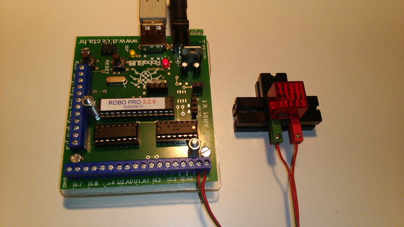
| PROGRAMMING SCHOOL | RoboPRO programs for RoboBUBI interface |
| 1. | PHOTO SENSOR - ANALOGUE (2) | 8. | TWO LIGHTS CONTROL WITH TWO MINI_SWITCH | ||||||
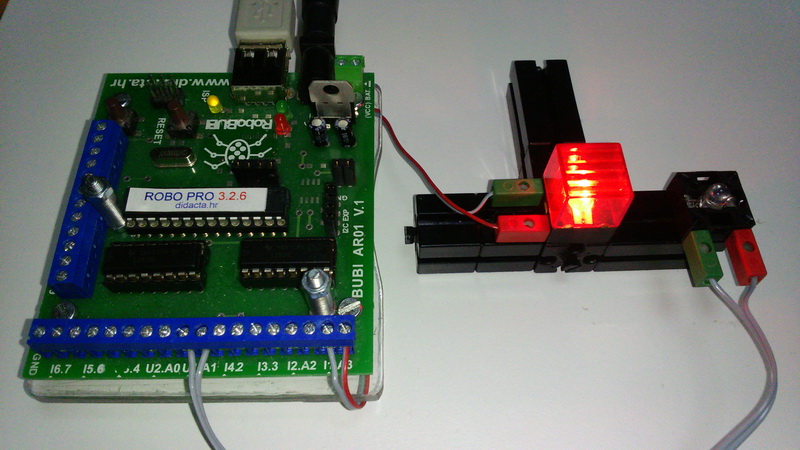
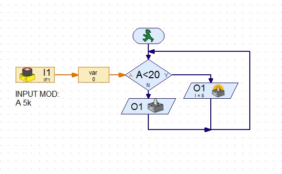
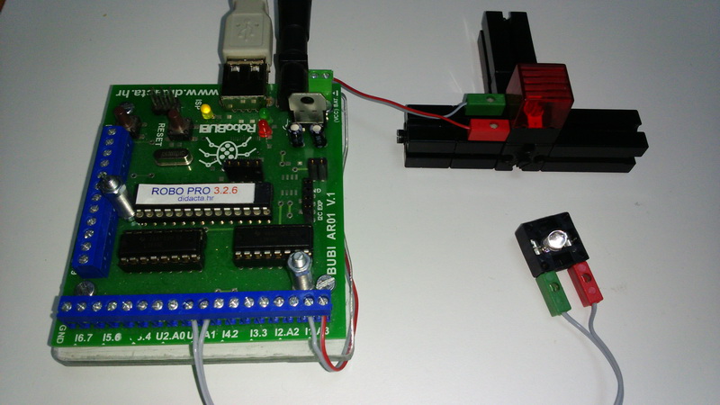
| 2. | FOTO SENSOR - ANALOGUE (1) | 9. | LIGHT CONTROL WITH MINI-SWITCH | ||||||
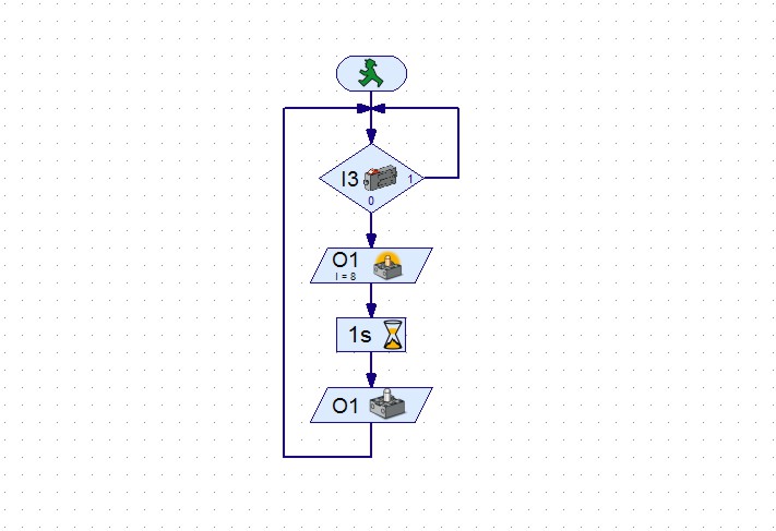
| 3. | IR SENSOR FISCHERTECHNIK - LINE (3) - MOTOR CONTROL | 10. | DC MOTOR CONTROL | ||||||
| 4. | IR SENSOR FISCHERTEHNIK - LINE (2) | 11. | THREE LIGHTS CONTROL - TRAFFIC LIGHT | ||||||
| 5. | IR SENSOR FISCHERTEHNIK - LINE (1) | 12. | TWO LIGHTS CONTROL | ||||||
| 6. | PHOTO SENSOR (TRANSISTOR) (2) | 13. | TWO LIGHTS CONTROL | ||||||
| 7. | PHOTO SENSOR (TRANSISTOR) (1) | 14. | LIGHT CONTROL | ||||||
| |||||||||||||||||||||||||||||||||||||||||||||||||||||||||||||||||||||||||||||||||||||||||||||||||||||||||||||||||||||||||||||||||||||||||||||||||||||||||||||||||||||||||||||||||||||||||||||||||||||||||||||||||||||||||||||||||||||||||||||||||||||||||||||||||||||||||||||||||||||||||||||||||||||||||||||||||||||||||||||||||||||||||||||||||||||||||||||||||||||||||||||||||||||||||||||||||||||||||||||||||||||||||||||||||||||||||||||||||||||||||||||||||||||||||||||||||||||||||||||||||||||||||||||||||||||||||||||||||||||||||||||||||||||||||||||||||||||||||||||||||||||||||||||||||||||||||||||||||||||||||||||||||||||||||||||||||||||||||||||||||||||||||||||||||||||||||||||||||||||||||||||||||||||||||||||||||||||||||||||||||||||||||||||||||||||||||||||||||||||||||||||||||||||||||||||||||||||||||||||||||||||||||||||||||||||||||||||||||||||||||||||||||||||||||||||||||||||||||||||||||||||||||||||||||||||||||||||||||||||||||||||||||||||||||||||||||||||||||||||||||||||||||||||||||||||||||||||||||