| PROGRAMMING SCHOOL | Raspberry Pi-F5 / T5 |
| 1. | LED LIGHT (DIGITALY) | 13. | HEAT SENSOR (ANALOGUE) | ||||||
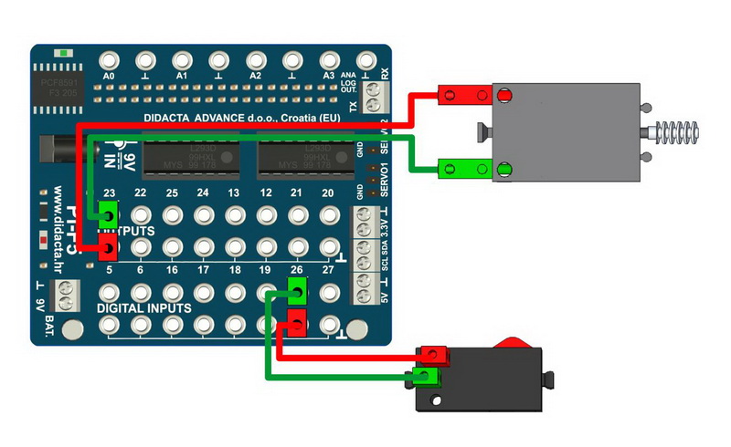
| 2. | LED LIGHT - MICRO SWITCH (DIGITAL) | 14. | MAGNETIC SENSOR (DIGITAL) | ||||||
| 3. | LED LIGHT (ANALOGUE) | 15. | COLOR SENSOR - COLORS | ||||||
| 4. | LED LIGHT - MICRO SWITHCH (ANALOGUE) | 16. | COLOR SENSOR - BLACK LINE | ||||||
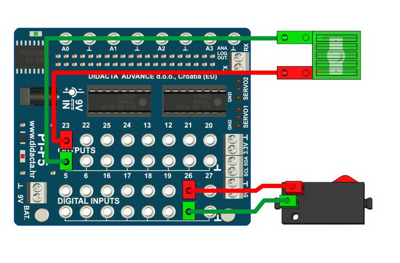
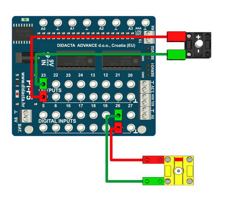
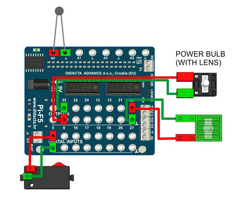
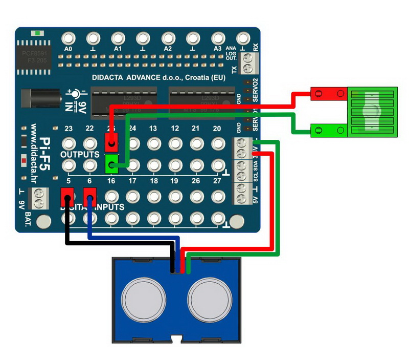
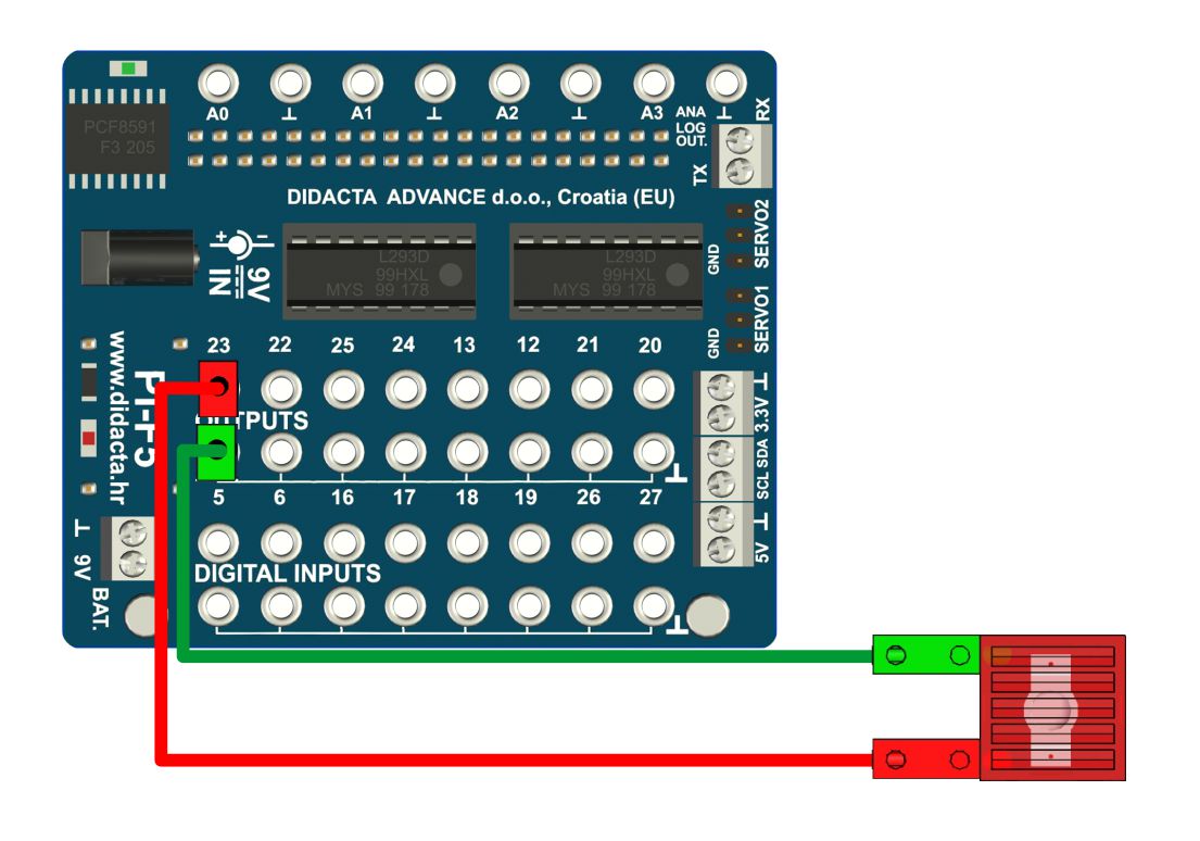
| 5. | PHOTO SENSOR - LED LIGHT (DIGITAL) | 17. | ULTRASOUND SENSOR (DIGITAL) | ||||||
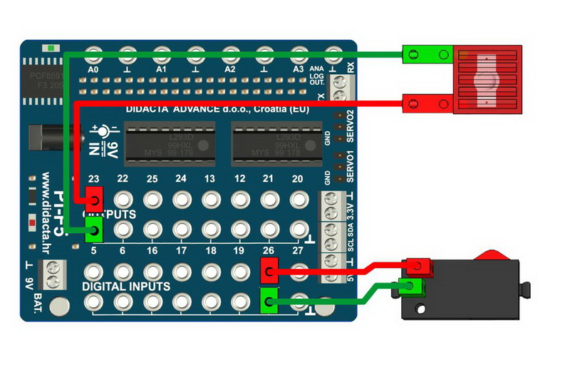
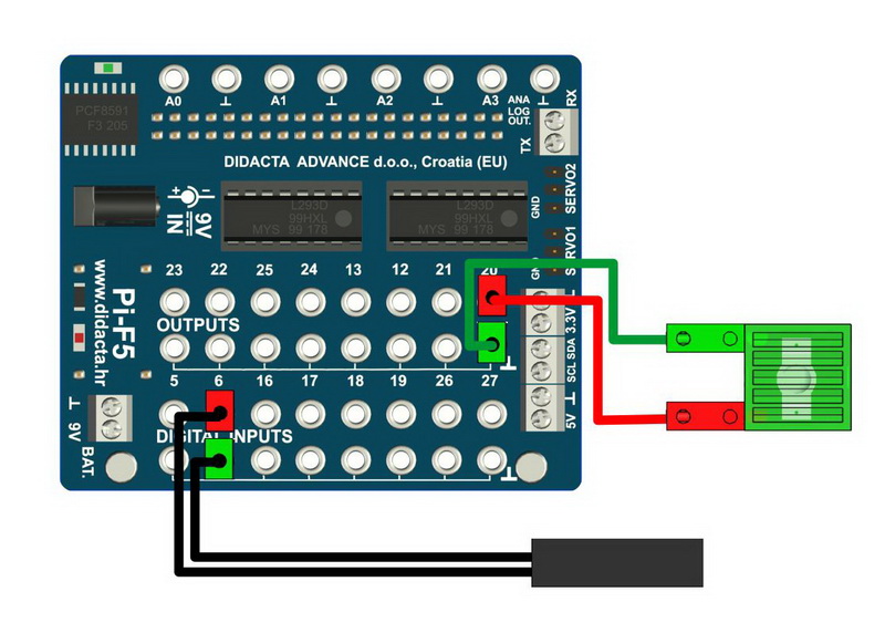
| 6. | PHOTO SENSOR - LED LIGHT (ANALOGUE) | 18. | ULTRASOUND SENSOR (ANALOGUE) | ||||||
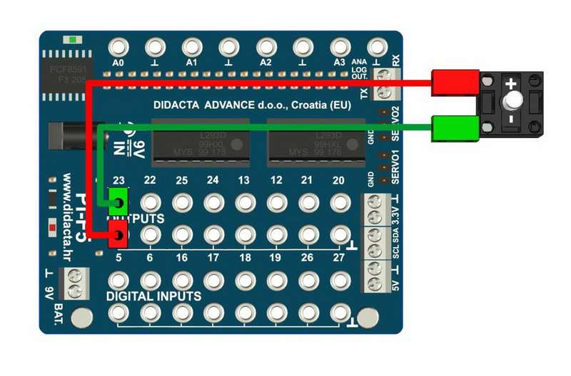
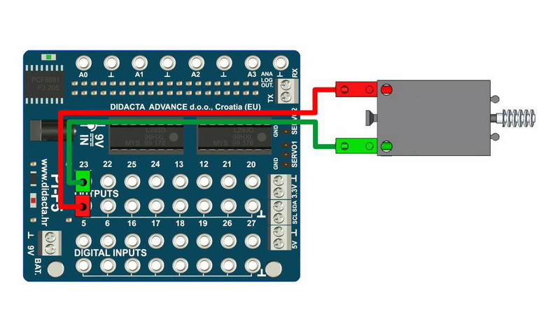
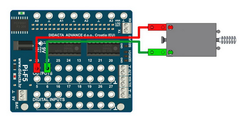
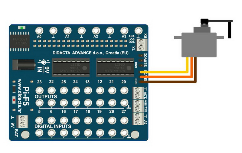
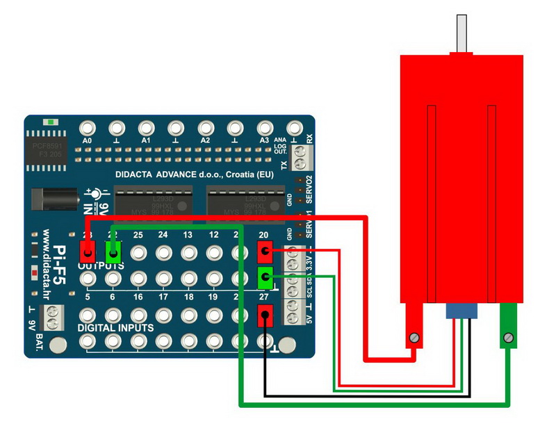
| 7. | DC MOTOR (DIGITAL) | 19. | SERVO MOTOR | ||||||
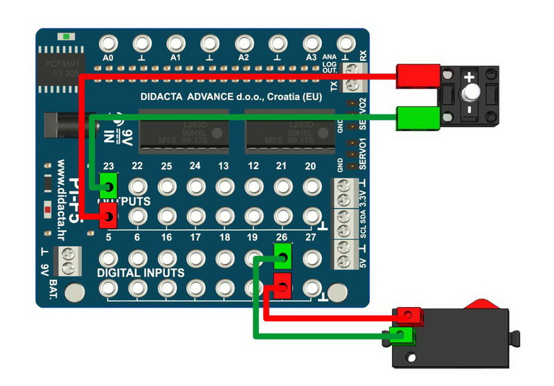
| 8. | DC MOTOR - ONE WAY ROTATION (DIGITAL) | 20. | I2C COMMUNICATION | ||||||
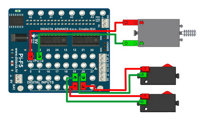
| 9. | DC MOTOR - TWO WAYS ROTATION (DIGITAL) | 21. | RX - TX COMMUNICATION | ||||||
| 10. | DC MOTOR - SPEED CONTROL (ANALOGUE) | 22. | ENCODER MOTOR - STEP - LESS PRECISE | ||||||
| 11. | IR SENSOR (DIGITAL) | 23. | ENCODER MOTOR - HALF STEP - BETTER PRECISION | ||||||
| 12. | IR SENSOR (ANALOGUE) | 24. | KAMERA - LED CONTROL (OPEN CV) | ||||||
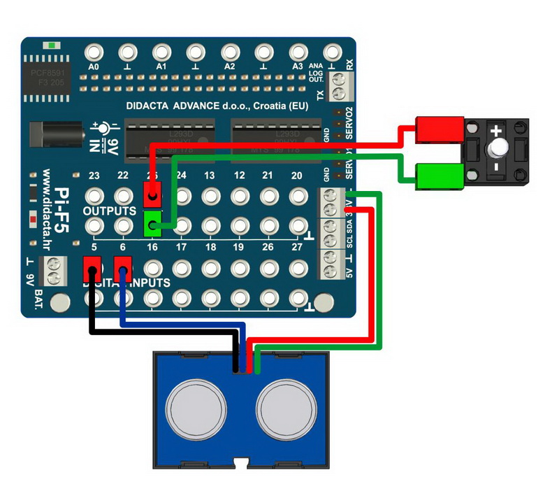
| |||||||||||||||||||||||||||||||||||||||||||||||||||||||||||||||||||||||||||||||||||||||||||||||||||||||||||||||||||||||||||||||||||||||||||||||||||||||||||||||||||||||||||||||||||||||||||||||||||||||||||||||||||||||||||||||||||||||||||||||||||||||||||||||||||||||||||||||||||||||||||||||||||||||||||||||||||||||||||||||||||||||||||||||||||||||||||||||||||||||||||||||||||||||||||||||||||||||||||||||||||||||||||||||||||||||||||||||||||||||||||||||||||||||||||||||||||||||||||||||||||||||||||||||||||||||||||||||||||||||||||||||||||||||||||||||||||||||||||||||||||||||||||||||||||||||||||||||||||||||||||||||||||||||||||||||||||||||||||||||||||||||||||||||||||||||||||||||||||||||||||||||||||||||||||||||||||||||||||||||||||||||||||||||||||||||||||||||||||||||||||||||||||||||||||||||||||||||||||||||||||||||||||||||||||||||||||||||||||||||||||||||||||||||||||||||||||||||||||||||||||||||||||||||||||||||||||||||||||||||||||||||||||||||||||||||||||||||||||||||||||||||||||||||