PROGRAMMING SCHOOL
RoboPro Coding - TXT 4.0
1. SERVO MOTOR9. ULTRASOUND sensor (1.)
2. ENKODER motor10. IR sensor
3. MOTOR - impulse gear11. PHOTO resistor (analog)
4. MOTOR speed control12. PHOTO transistor
5. MOTOR control with switches13. The LED lights up via a switch
6. MAGNETIC sensor14. Analog LED control
7. COLOR sensor15. Turn on the digital LED
8. ULTRASOUND sensor (2.)

SERVO MOTOR
Sh15.jpg

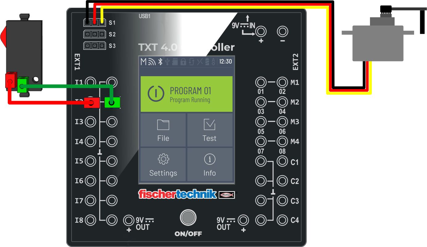
Connect the servo motor to S1 and the switch to I2. An example of moving and positioning a servo motor. The value for the starting position is 240.

ENKODER motor
Sh14.jpg

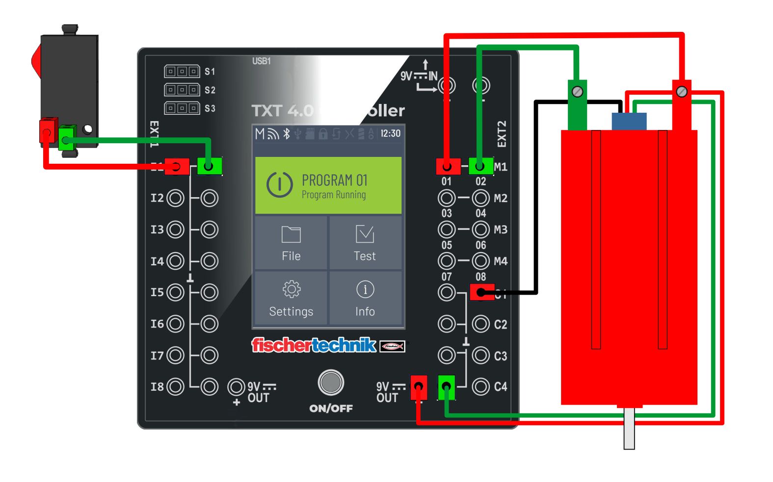
The encoder motor has a built-in hall sensor that counts the revolutions of the motor. At higher rotational speeds and the time required to stop the motor, positioning may be less accurate than positioning at lower rotational speeds.

MOTOR - impulse gear
Sh13.jpg

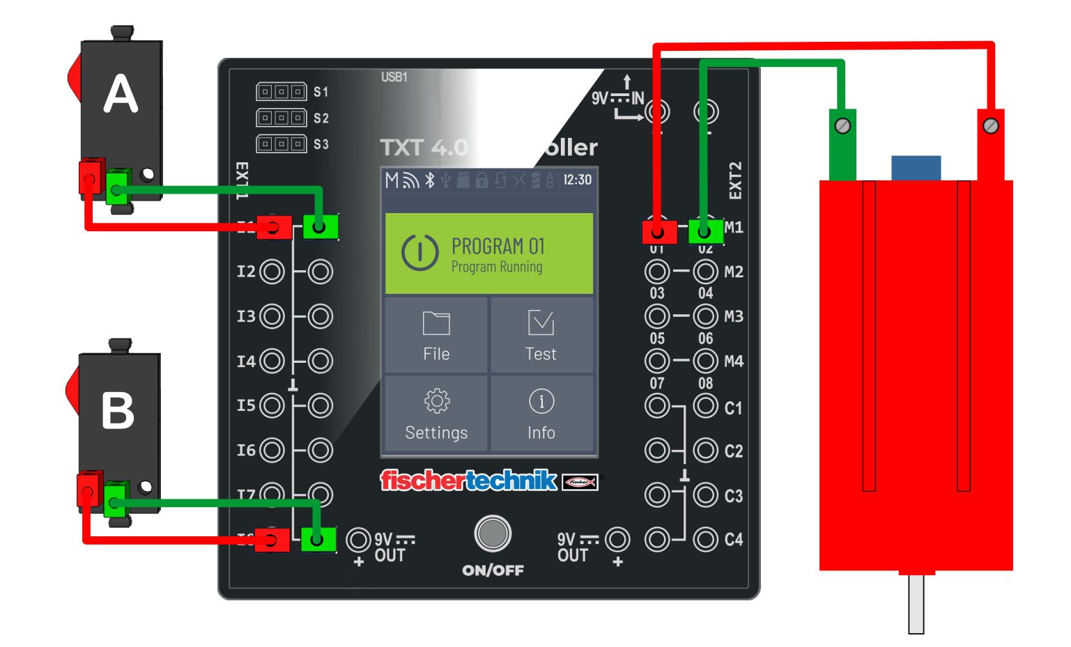
For precise positioning, we can use a step gear. The example shows positioning by 90 degrees in relation to the previous position. With the step gear, we can count how many times the button was pressed (ON) and how many times it was not (OFF). In this way, the positioning is more precise, due to the initial position, which can be ON or OFF. This example counts only when the button is pressed (ON position). Switch B counts the steps, switch A starts the motor.

MOTOR speed control
Sh12.jpg

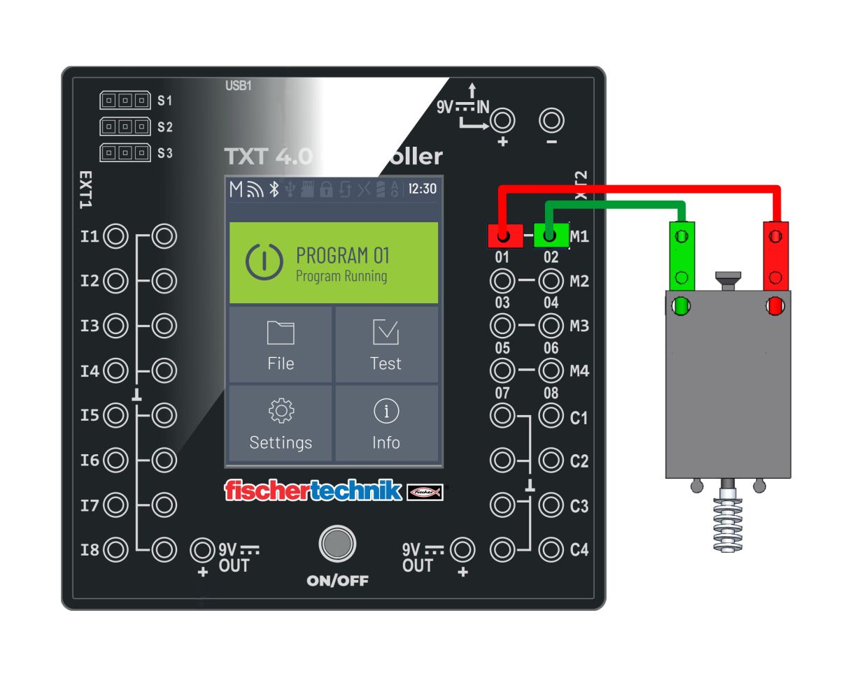
Motor speed control in steps of 100 (5 speeds). The maximum speed (motor speed) of revolutions is at the value 512, and the lower the value, the lower the number of revolutions of the engine. At a certain value, the motor stops because the power supply does not have enough power to start it.

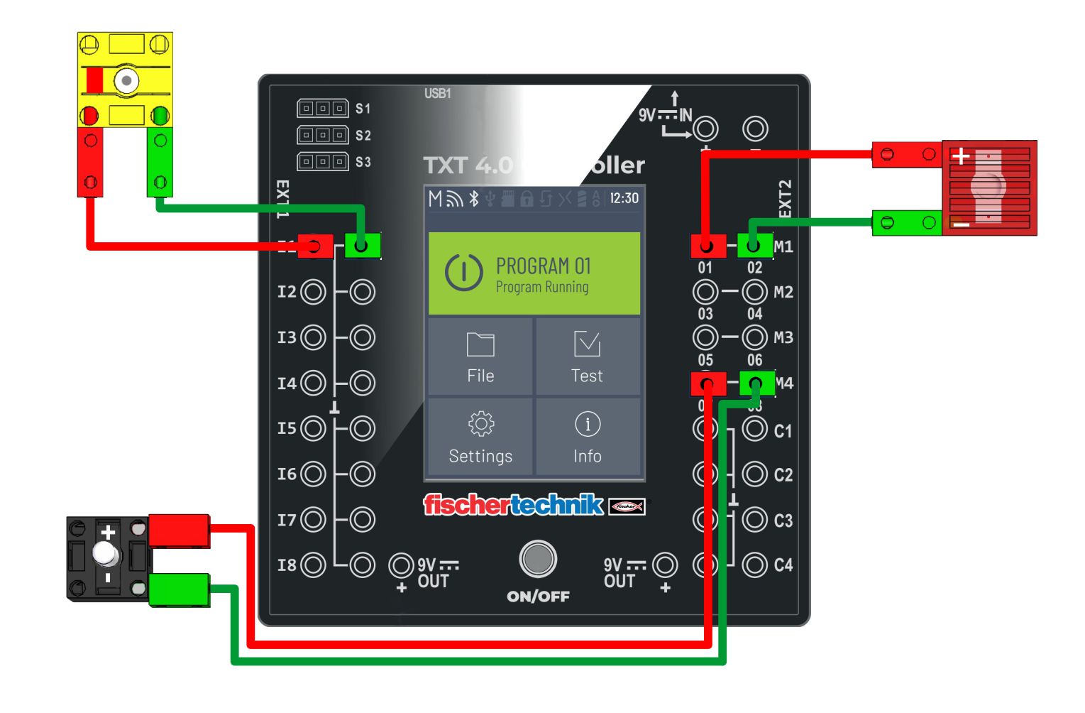
MOTOR control with switches
Sh11.jpg

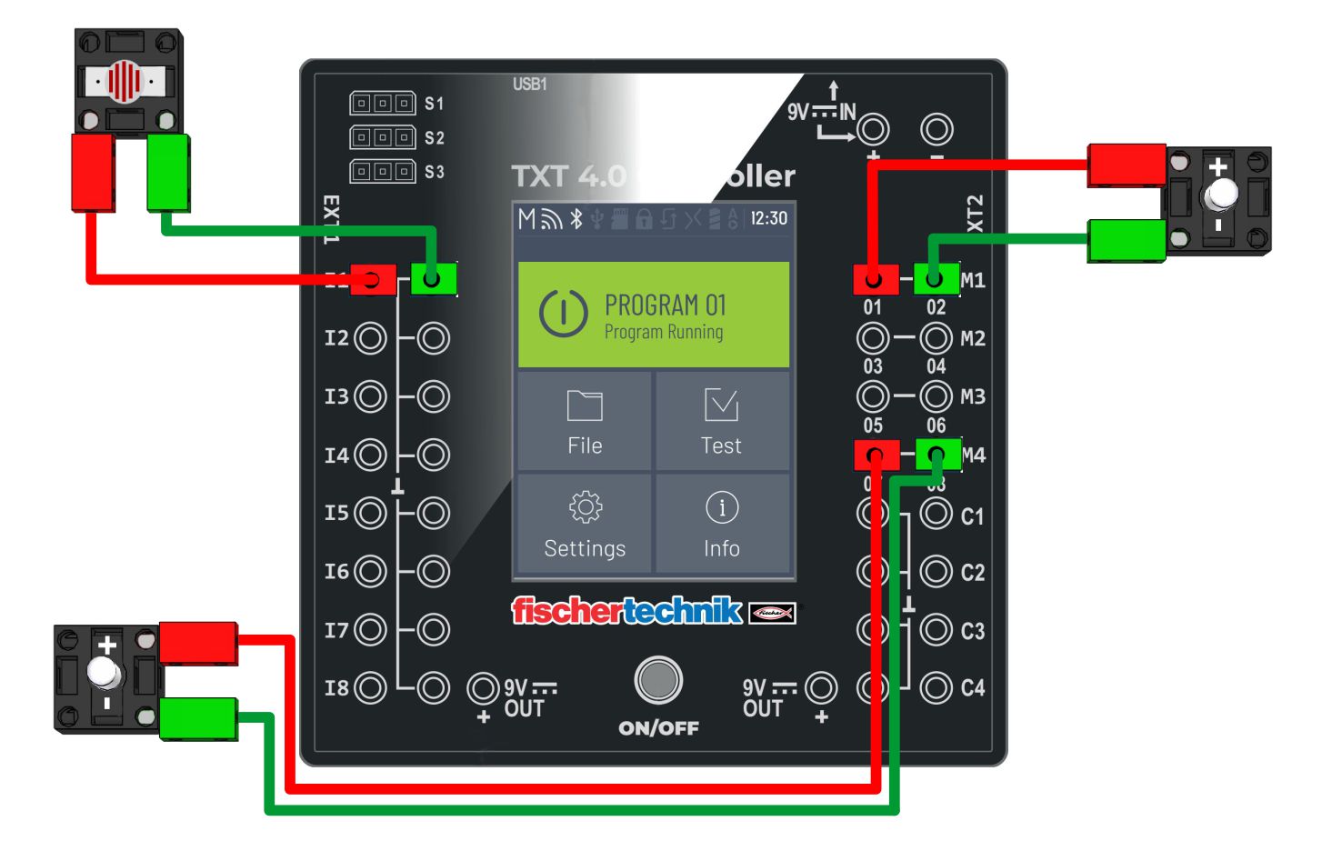
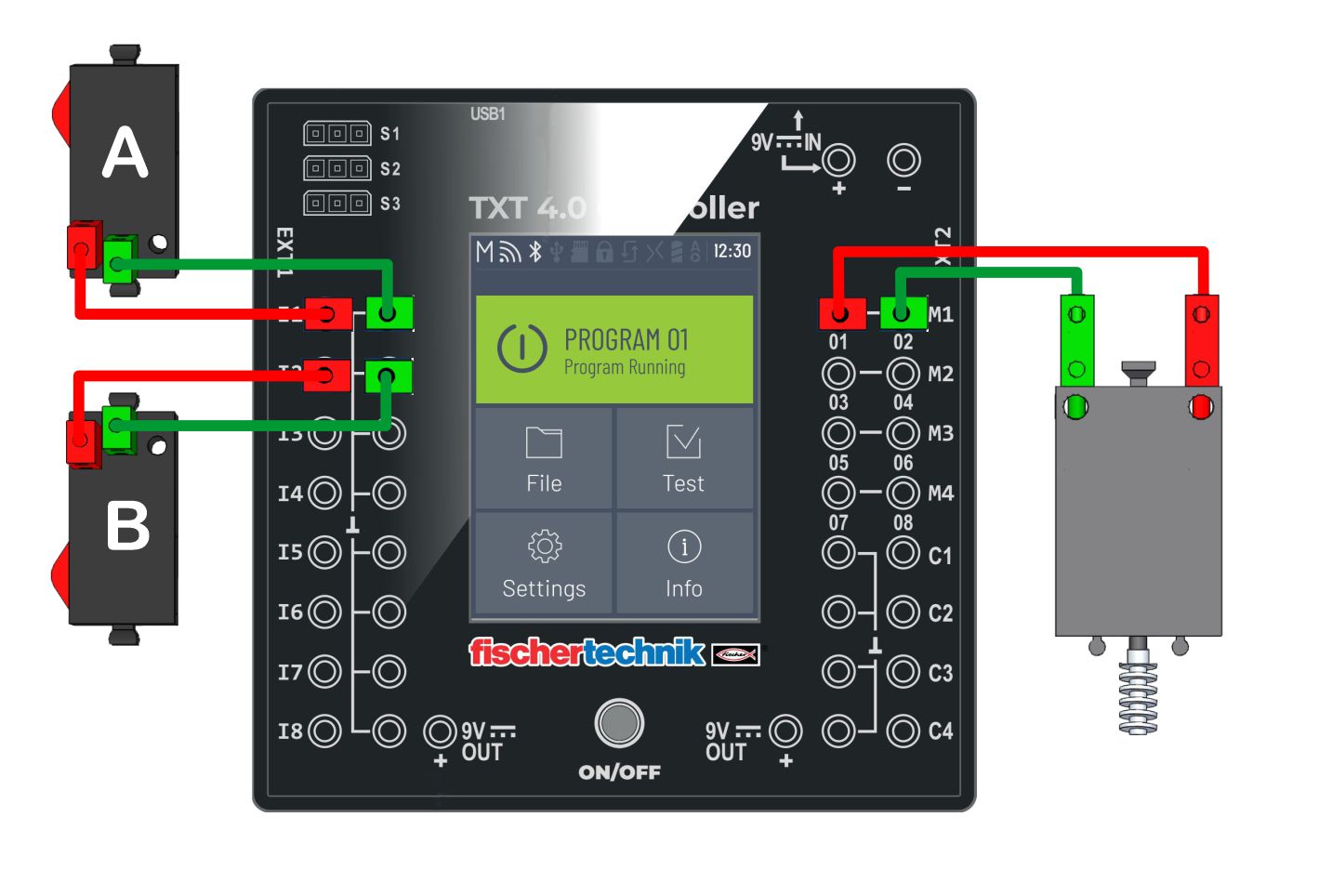
By pressing the switch A, the motor rotation is to the left, and by pressing the switch B, the rotation is to the right.

MAGNETIC sensor
Sh10.jpg

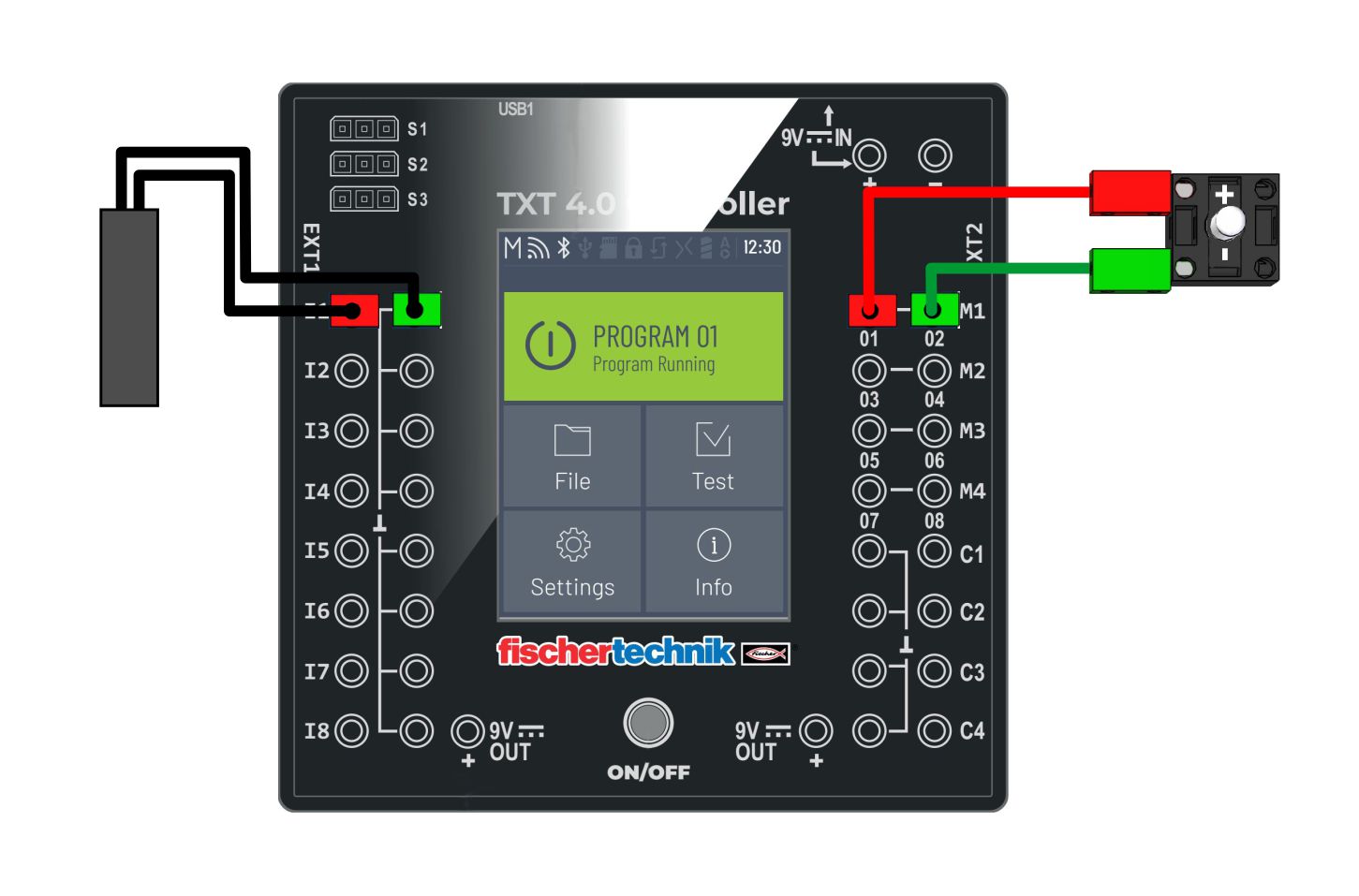
The magnetic sensor detects the magnetic field. Bringing the magnet closer to the sensor lights up the LED, and moving away turns it off.

COLOR sensor
Sh09.jpg

In order for the COLOR sensor to work correctly and for the values for different colors to be large enough, it is necessary to place the sensor at the correct distance from the substrate. The surrounding lighting can also be a problem (depending on the type of light). The values for the colors in this example are adapted to the background used in the exercise.

ULTRASOUND sensor (2.)
Sh08.jpg

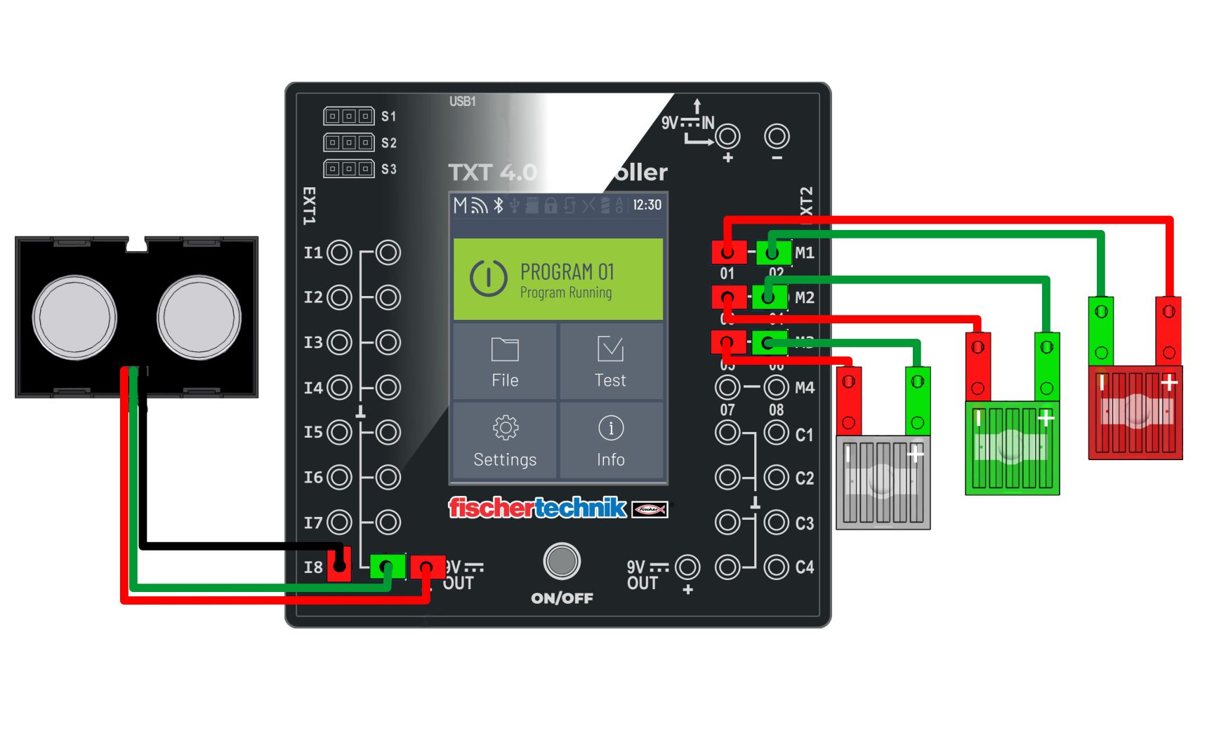
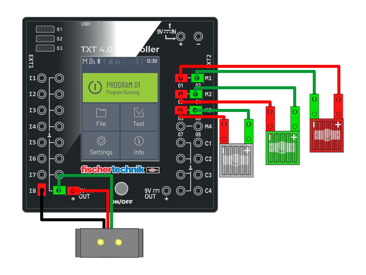
Led lights are turned off according to the distance from the obstacle. If the distance is less than 30 cm, the white LED turns off. If the distance is less than 20 cm, the green LED turns off. If the distance is less than 10 cm, the red LED turns off.

ULTRASOUND sensor (1.)
Sh07.jpg

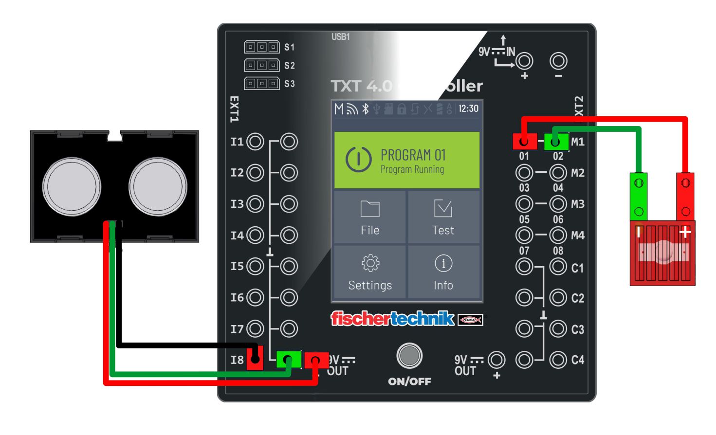
When the ultrasonic sensor detects an obstacle at a distance of less than 10 cm, the LED light turns on.

IR sensor
Sh06.jpg

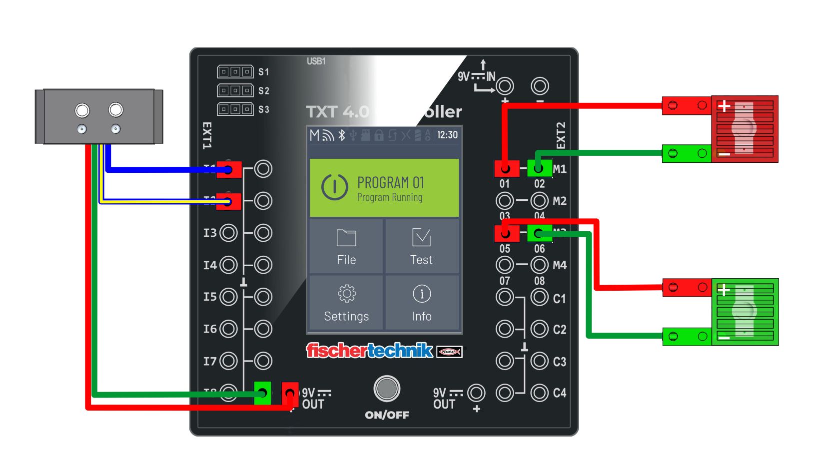
The IR sensor (module) consists of two sensors. When the sensor is illuminated, the LED lights up, and when it is not, it turns off. The white surface reflects the light on the sensor and the LED lights up. The black background (line) does not reflect light and the LED light goes out.

PHOTO resistor (analog)
Sh05.jpg

The brightness of the LED depends on the brightness of the PHOTO resistor.

PHOTO transistor
Sh04.jpg

When the brightness of the FOTO transistor is high enough, the LED lights up.

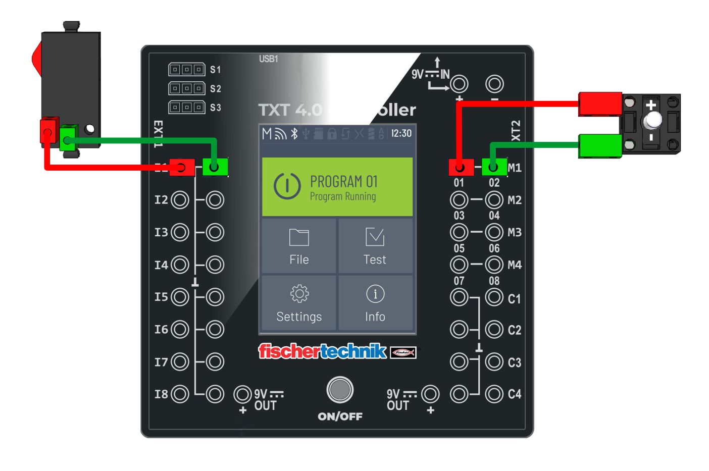
The LED lights up via a switch
Sh03.jpg

By pressing the switch, the LED light turns on, and when it stops, it turns off.

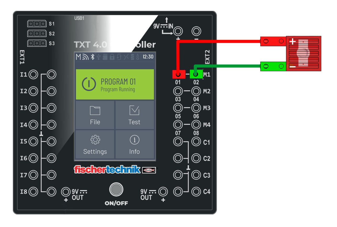
Analog LED control
Sh02.jpg

Increasing and decreasing the brightness of the LED light in steps (64). You can decrease the step value if you want to get a smoother transition.

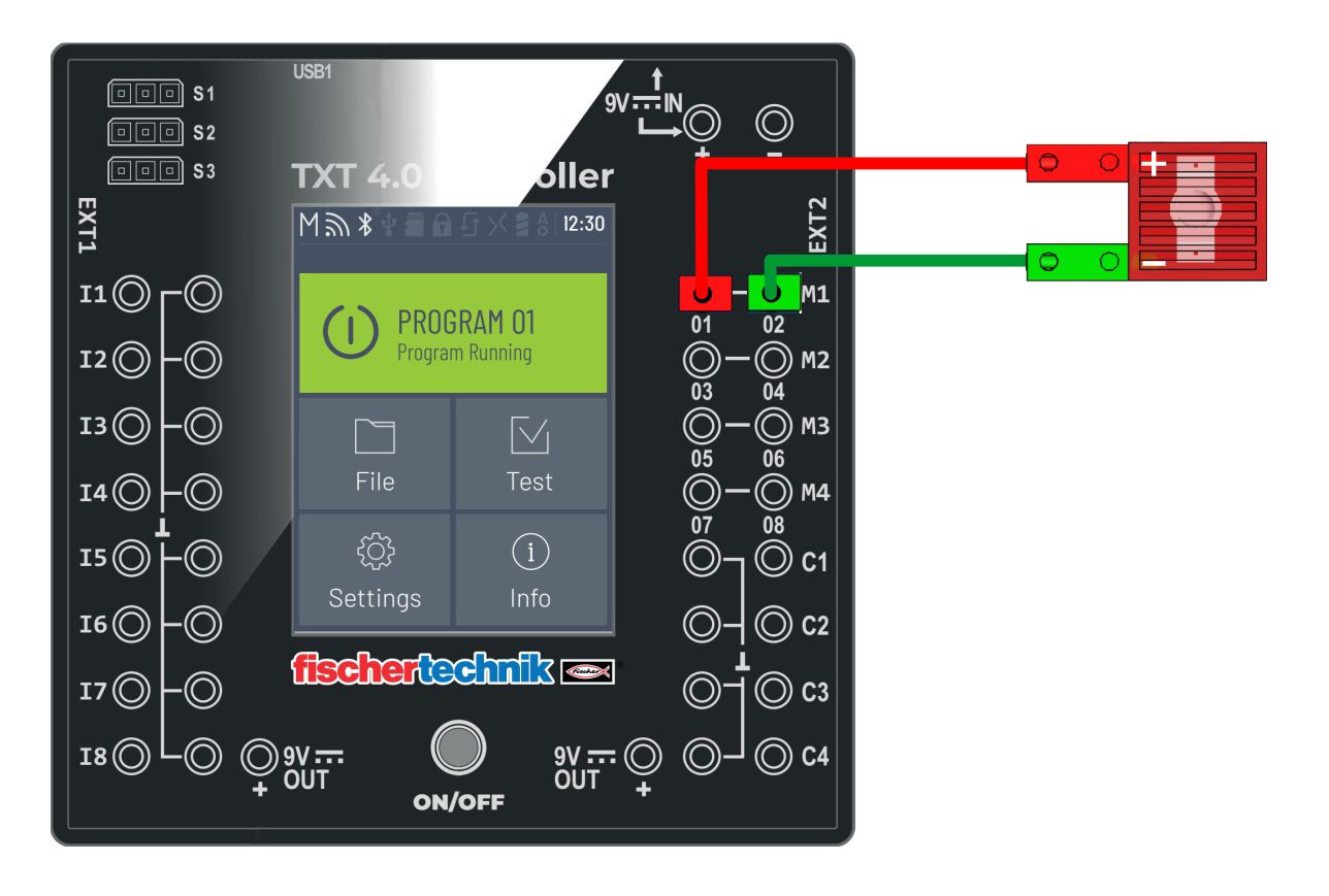
Turn on the digital LED
Sh01.jpg

Turns the LED light on and off in half a second.