| PROGRAMMING SCHOOL | ProgBlox Set - examples |
| 1. | Example 11 - car dance | 7. | Ramp - saved program from example 2 | ||||||
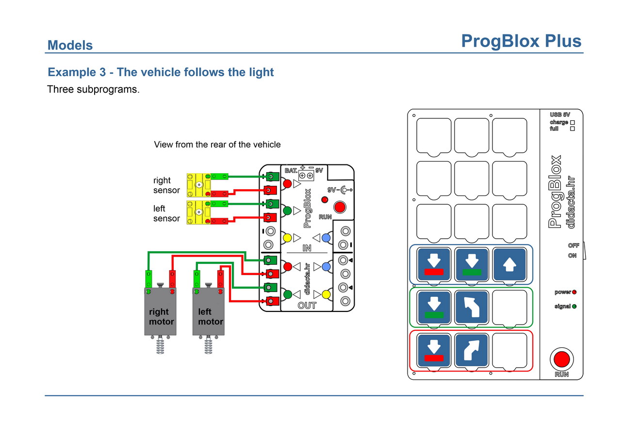
| 2. | Example 10 - Conveyor belt with magnetic sensor | 8. | Example 3 - The vehicle follows the light | ||||||
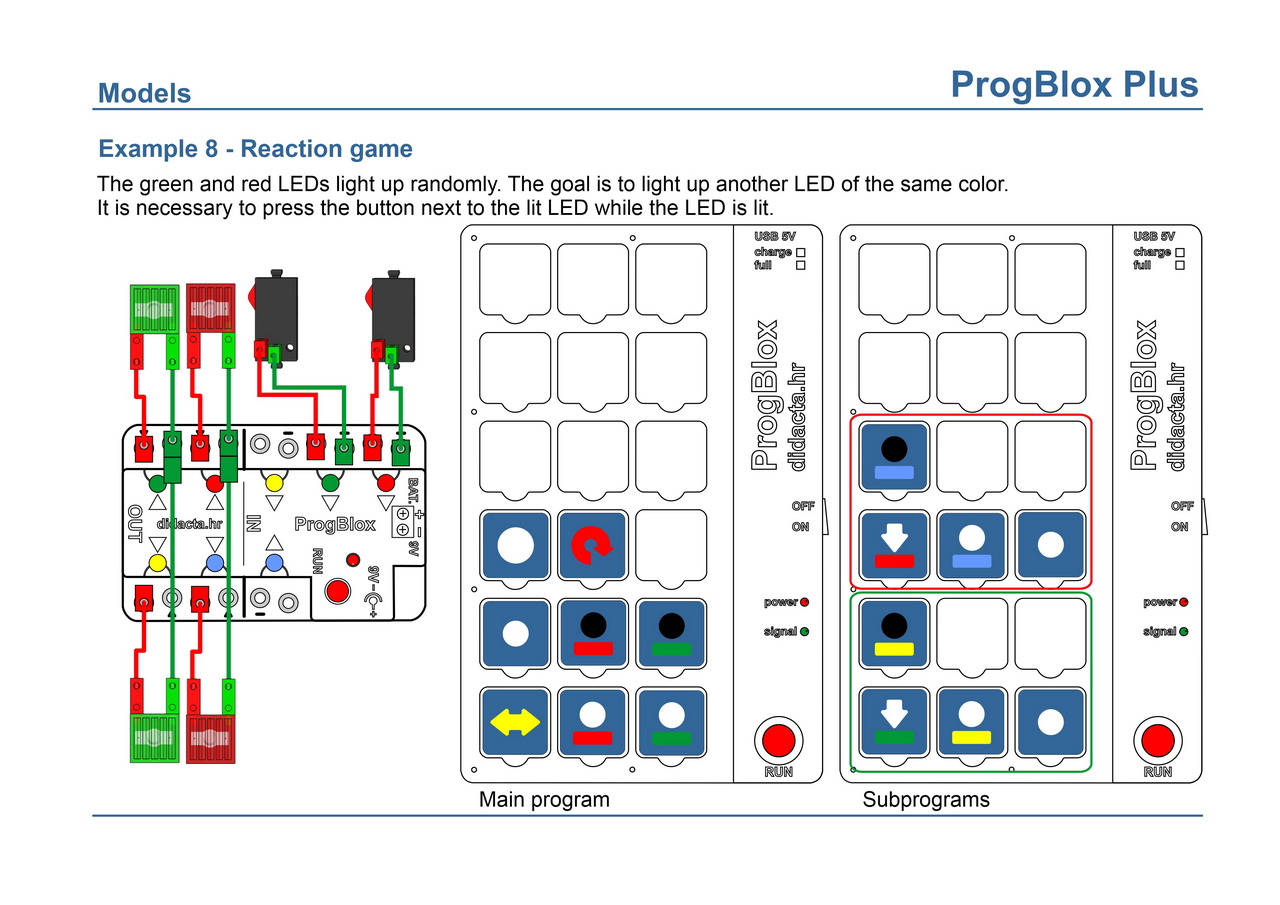
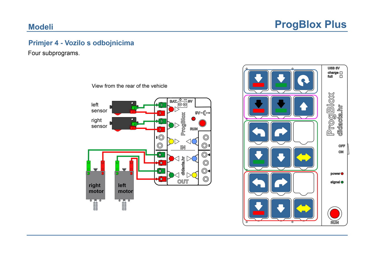
| 3. | Example 8 - Reaction game | 9. | Example 4 - A vehicle with bumpers - an advanced example | ||||||
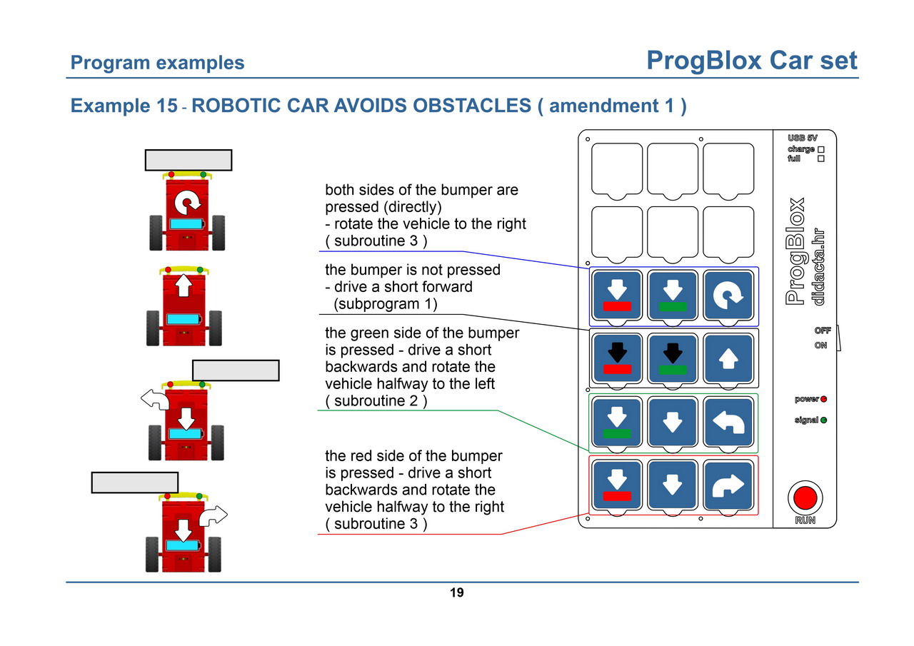
| 4. | Example 9 - Forklift on robo Car | 10. | Exemple 5 - Vehicle - Car set - supplemented example 15 (1) | ||||||
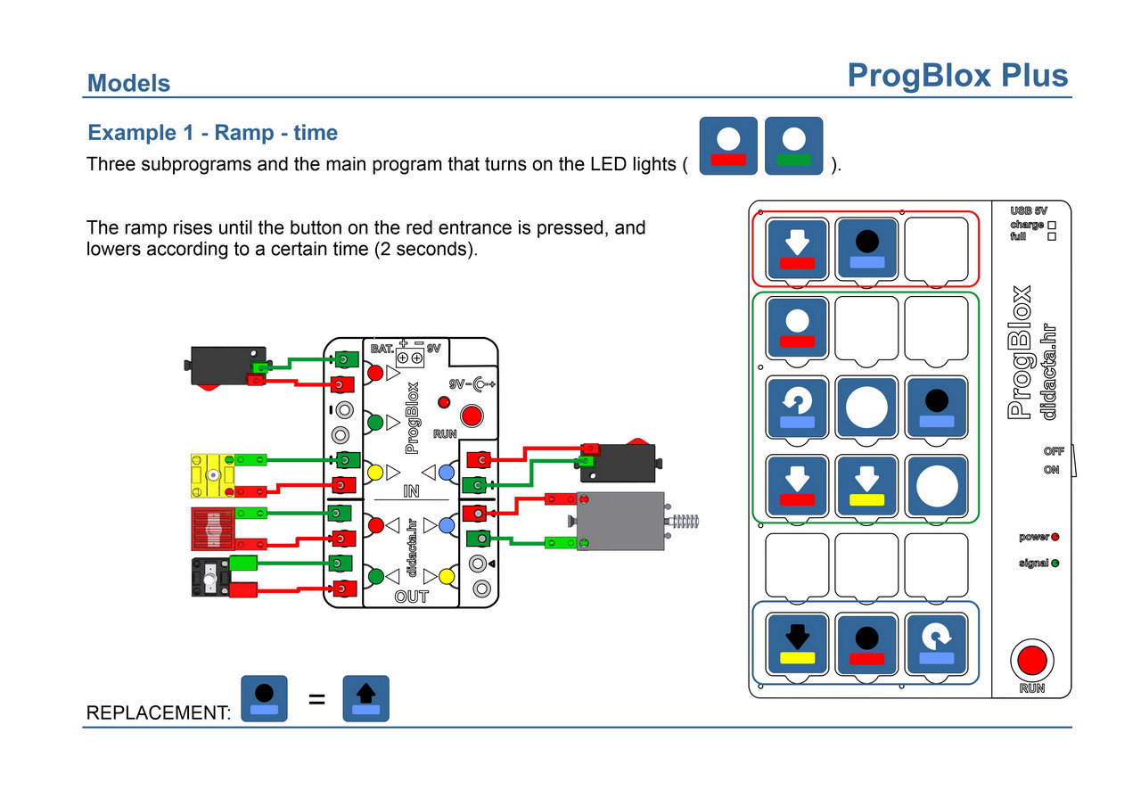
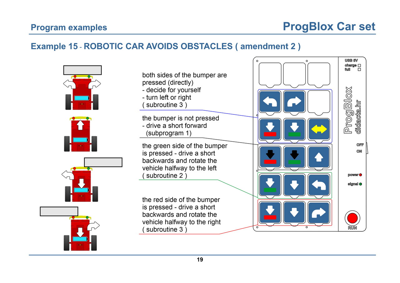
| 5. | Example 1 - Ramp - 1 limit switch | 11. | Exemple 6 - Vehicle - Car set - supplemented example 15 (2) | ||||||
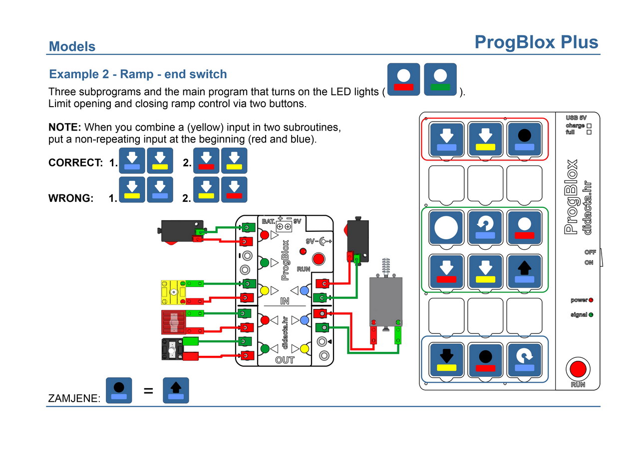
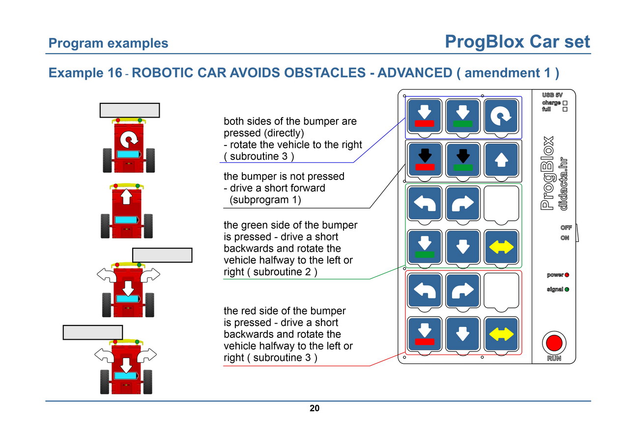
| 6. | Example 2 - Ramp - 2 limit switches | 12. | Example 7 - Vehicle - Car set - supplemented example 16 (1) | ||||||